1. Introduktion
The Neoteck Digital Bore Gauge Set TL338 is a precision instrument designed for accurate measurement of internal diameters, particularly suitable for deep engine cylinder measurements. It features a digital indicator for clear readings, self-centering capabilities, durable carbide anvils, and insulated grips for comfortable and reliable operation.
Nøglefunktioner:
- Accurate Digital Indicator: Diameter Range: 0 ~ 12.7mm (0 ~ 0.5 inch); Resolution: 0.01mm (0.0005 inch).
- Precise Bore Gauge: Measuring Diameter Range: 50mm-160mm (2-6 inch); Measuring Depth: 150mm (5.9 inch); Accuracy: 0.01mm (0.0005 inch).
- Self-Centering Design: Ensures fast and accurate measurements.
- Durable Construction: All-metal clamping device, aluminum housing, glass mirror cover, wear-resistant probes, and carbide anvils.
- User-Friendly: Insulated grip for easier handling, clear digital display, inch/mm conversion, and zero-setting function.
Pakkeindhold:
- 1 x Digital Dial Indicator (0.5 inch)
- 1 x Measuring Rod
- 1 x Set of Measuring Accessories (various gauge sizes: 50mm, 55mm, 60mm, 65mm, 70mm, 75mm, 80mm, 85mm, 90mm, 95mm, 100mm, 105mm, plus 0.5mm, 1mm, 2mm, 3mm spacers)
- 1 x opbevaringskasse

The complete Neoteck Digital Bore Gauge Set, including the main gauge assembly, interchangeable measuring probes, and a protective storage case.

The robust storage case, designed to protect and organize all components of the bore gauge set, including the digital indicator, measuring rod, and various probes.
2. Opsætning
2.1 Digital Indicator Installation
- Carefully remove the digital indicator from its protective case.
- Remove the protective cap from the indicator's measuring spindle.
- Insert the digital indicator into the top opening of the measuring rod, ensuring it is securely seated.
- Spænd clamping handle on the measuring rod to firmly hold the indicator in place.

Detaljeret view of the digital indicator, highlighting its clear LCD display, unit conversion (inch/mm) and zero buttons, and durable internal construction for stable measurements.
2.2 Measuring Rod and Probe Assembly
- Select the appropriate measuring probe (anvil) and any necessary spacers from the accessory set based on the approximate diameter of the bore you intend to measure. The set includes various sizes from 50mm to 105mm, along with 0.5mm, 1mm, 2mm, and 3mm spacers for fine adjustment.
- Screw the selected probe and spacers onto the bottom end of the measuring rod. Ensure they are finger-tight to prevent movement during measurement.
- Verify that the probe's contact points are clean and free from debris.

Illustrates the stable locking mechanism that secures the digital indicator to the measuring rod, and the wear-resistant probe designed for durability and accuracy during measurements.
3. Betjeningsvejledning
3.1 Power On and Unit Selection
- Press the 'ON/OFF' button on the digital indicator to power it on.
- Press the 'inch/mm' button to switch between imperial (inches) and metric (millimeters) units as required for your measurement.
3.2 Zero Setting (Calibration)
Before taking any measurements, the gauge must be zeroed using a master ring gauge or a known standard of the target bore size. This ensures accuracy.
- Insert the assembled bore gauge into a master ring gauge of the desired nominal diameter.
- Gently rock the gauge back and forth within the master ring to find the minimum reading. This ensures the self-centering mechanism is engaged and the gauge is perpendicular to the bore axis.
- While holding the gauge at its minimum reading, press the 'ZERO' button on the digital indicator. The display should now read '0.000' (or '0.0000' depending on resolution). The gauge is now calibrated to the master ring gauge.
3.3 Tage en måling
- Carefully insert the calibrated bore gauge into the bore you wish to measure.
- Gently rock the gauge back and forth across the bore's diameter to find the minimum reading on the digital display. This minimum reading represents the true diameter at that specific depth.
- Take measurements at various depths and orientations (e.g., top, middle, bottom; 0°, 90°) within the bore to check for taper, ovality, and overall consistency.
- Record your measurements. The displayed value indicates the deviation from the master ring gauge's diameter. For example, if the master ring was 50mm and the gauge reads +0.02mm, the bore is 50.02mm.

A visual guide illustrating the four key steps for using the bore gauge: installing the indicator, attaching the measuring probe, calibrating the indicator, and performing a measurement.

An annotated diagram showing the main parts of the bore gauge, including the digital indicator, clamping handle, insulated handle, straight pipe, and probe, along with its measuring diameter range and depth.
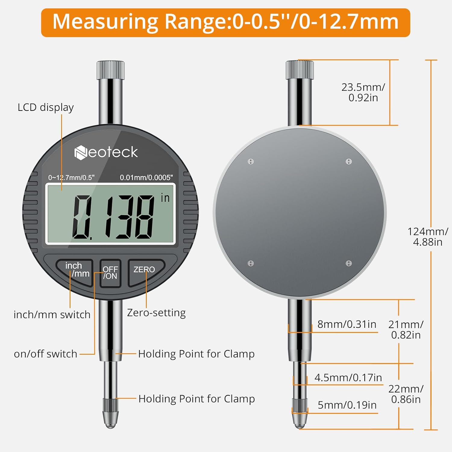
A detailed diagram of the digital indicator, indicating the LCD display, inch/mm switch, on/off switch, zero-setting button, and holding points for clamping, along with its physical dimensions.
4. Vedligeholdelse
4.1 Rengøring
- After each use, wipe all components of the bore gauge with a clean, soft, dry cloth to remove any dust, oil, or debris.
- For stubborn grime, a cloth lightly dampened with isopropyl alcohol can be used, ensuring no liquid enters the digital indicator.
- Do not use harsh chemicals or abrasive materials, as these can damage the finish or precision components.
4.2 Opbevaring
- Always store the bore gauge set in its original protective case when not in use.
- Store in a dry, clean environment, away from direct sunlight, extreme temperatures, and high humidity.
- Ensure the digital indicator is powered off before storage to conserve battery life.
4.3 Udskiftning af batteri
- If the digital display becomes dim or unresponsive, the battery may need replacement.
- Refer to the digital indicator's specific instructions for battery type and replacement procedure. Typically, this involves unscrewing a small battery cover on the back of the indicator.
- Bortskaf gamle batterier på en ansvarlig måde.
5. Fejlfinding
5.1 Unøjagtige aflæsninger
- Incorrect Probe/Spacer Selection: Ensure the correct measuring probe and spacers are used for the nominal bore size.
- Improper Zero Setting: Re-calibrate the gauge using a known master ring gauge. Ensure the minimum reading is found before zeroing.
- Debris on Contact Points: Clean the measuring probes and anvils thoroughly.
- Improper Measurement Technique: Ensure the gauge is gently rocked to find the true minimum diameter and that it is perpendicular to the bore axis.
- Temperatursvingninger: Allow the gauge and workpiece to stabilize at the same ambient temperature before measuring.
5.2 Digital Display Issues
- Blank eller svag skærm: Replace the battery in the digital indicator.
- Uregelmæssige læsninger: Check for loose connections between the indicator and the measuring rod. Ensure the indicator is securely clampudg.
- Display Not Changing: Ensure the measuring spindle moves freely and is not obstructed.
6. Specifikationer
| Feature | Specifikation |
|---|---|
| Modelnummer | TL338 |
| Digital Indicator Range | 0 ~ 12.7 mm (0 ~ 0.5 tommer) |
| Digital Indicator Resolution | 0.01 mm (0.0005 tommer) |
| Bore Gauge Measuring Diameter Range | 50mm-160mm (2-6 inch) |
| Måle dybde | 150 mm (5.9 tommer) |
| Nøjagtighed | 0.01 mm (0.0005 tommer) |
| Materiale | Aluminum (body), Carbide (anvils) |
| Pakkedimensioner | 15.51 x 6.26 x 2.64 tommer |
| Varens vægt | 2.76 pund |
7. Garanti og support
This Neoteck product is covered by a standard manufacturer's warranty. For warranty claims, technical support, or service inquiries, please refer to the contact information provided with your purchase or visit the official Neoteck webwebsted. Gem venligst din købsbevis af garantihensyn.


