1. Introduktion
The TOOLTOP MH14 Digital Resistance Meter is a professional instrument designed for testing the grounding resistance of electrical equipment. This device features an improved circuit, structure, and process compared to traditional grounding resistance testers, offering enhanced functionality, higher accuracy, and more convenient operation. Its dust-proof and moisture-proof design makes it suitable for field use.
The MH14 can measure grounding resistance values for various power systems, power equipment, lightning protection equipment, and other grounding systems, as well as AC voltage.
Key characteristics include an LCD display with 1999 counts and an over-range indication where only the highest digit displays "1" when the upper limit is exceeded.

Figure 1.1: The TOOLTOP MH14 Digital Resistance Meter with its included accessories, showcasing the main unit, test leads, ground rods, and carrying case.
2. Sikkerhedsoplysninger
Always adhere to local and national safety regulations when operating this device. Failure to do so may result in injury or damage to the equipment.
- Sørg for, at enheden er i god stand før hver brug.
- Do not operate the meter in wet environments or in the presence of explosive gases or dust.
- Always disconnect power to the circuit before making connections for resistance measurements.
- Use only the provided test leads and accessories.
- Do not exceed the maximum input ratings specified in the technical specifications.
- If the "1" over-range indication appears, the measured value exceeds the meter's range.
3. Produktfunktioner
- Digital Megohmmeter Electronic Megameters with 2000 Counts Insulation Resistance Testers.
- Features a low-loss, high-ratio inductance energy storage DC voltage konverter.
- Utilizes a digital LCR bridge for resistance measurement and insulation resistance testing.
- Advanced design ensures stable performance.
- User-friendly and hands-free operation, designed with a shoulder strap for ease of use.

Figure 3.1: The included carrying case features an adjustable shoulder strap, nylon zipper, and Velcro tape for secure and convenient transport. Dimensions are approximately 170mm (6.69 inches) in all three dimensions.
4. Pakkens indhold
Følgende varer er inkluderet i pakken:
- 1 x TOOLTOP MH14 Digital Resistance Meter
- Test Leads (Red, Green, Yellow)
- Ground Rods (2 pieces)
- Bæretaske
- Brugervejledning (dette dokument)

Figure 4.1: All components included in the MH14 package, neatly arranged.
5. Opsætning og drift
5.1. Batteriinstallation
The MH14 meter requires eight AA batteries for operation. Locate the battery compartment on the back of the device, open it, and insert the batteries according to the polarity indicators. Close the compartment securely.
5.2. Ground Voltage Måling
To measure AC ground voltage:
- Connect the red test lead to the "V" terminal and the black test lead to the "ECOM" terminal on the meter.
- Insert one ground rod into the earth at a distance of approximately 10 meters from the ECOM connection point.
- Connect the red test lead to the ground rod.
- Connect the black test lead to the ECOM point (e.g., a known ground point or another ground rod 5 meters away from the meter).
- Turn the rotary switch to the "EARTH VOLTAGE" position.
- Press the "PRESS TO TEST" button to initiate the measurement. The AC voltage vil blive vist på LCD'et.

Figure 5.1: Diagram illustrating the setup for ground voltage testing, showing the meter, test leads, and ground rods positioned for measurement.
5.3. Ground Resistance Measurement (Three-Point Method)
To measure ground resistance using the three-point method:
- Connect the green test lead to the "E" terminal, the yellow test lead to the "P" terminal, and the red test lead to the "C" terminal on the meter.
- Insert the "E" ground rod (connected to green lead) into the earth at the point of measurement.
- Insert the "P" ground rod (connected to yellow lead) into the earth approximately 5 meters away from the "E" rod.
- Insert the "C" ground rod (connected to red lead) into the earth approximately 10 meters away from the "E" rod, ensuring all three rods are in a straight line.
- Turn the rotary switch to the desired resistance range (20Ω, 200Ω, 2000Ω, or 20000Ω).
- Press the "PRESS TO TEST" button to initiate the measurement. The ground resistance value will be displayed.
- Press "HOLD" to freeze the displayed reading.

Figure 5.2: Diagram illustrating the setup for grounding resistance testing using the three-point method, showing the meter, test leads, and ground rods positioned for measurement.
5.4. Simple Ground Resistance Test (Two-Point Method)
This method is suitable for occasions where auxiliary grounding rods cannot be used, such as testing the resistance of a water pipe or a metal structure that is already grounded.
- Connect the green test lead to the "E" terminal and the red test lead to the "C" terminal on the meter.
- Connect the green test lead to the ground point of the object under test (Rx).
- Connect the red test lead to a known good ground reference point (re), such as a water pipe or building ground.
- Turn the rotary switch to the desired resistance range.
- Press the "PRESS TO TEST" button to initiate the measurement. The resistance value will be displayed.
Figure 5.3: Diagram illustrating the simple ground resistance test method, connecting the meter to the object under test and a known ground reference.
6. Specifikationer
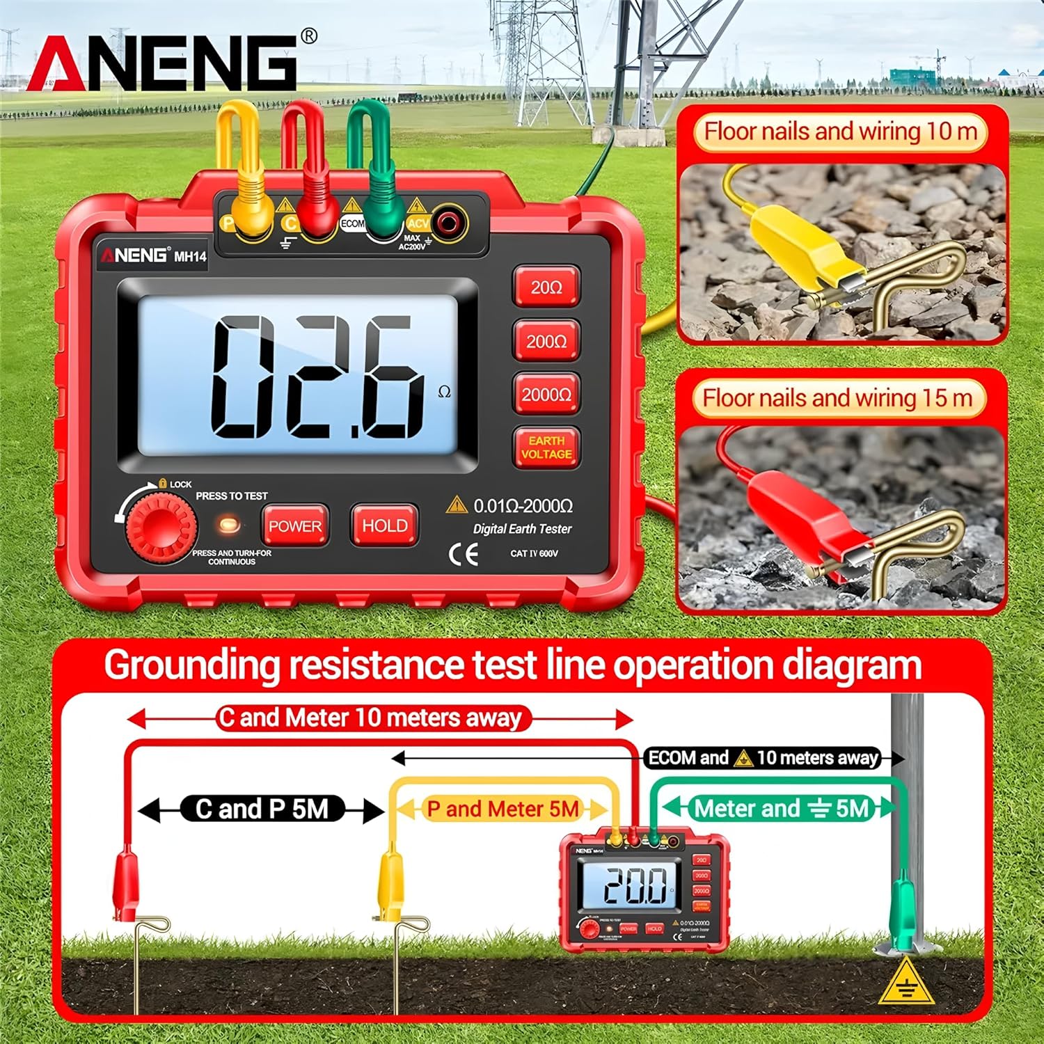
Figure 6.1: Detailed specifications table for the MH14 Digital Earth Tester, including range, accuracy, resolution, and general characteristics.
| Karakteristisk | Værdi |
|---|---|
| Vise | LCD, 1999 tæller |
| Over-range indikation | "1" displayed for highest digit |
| Batteri model | Eight AA batteries |
| Materiale | Silicone sheath/ABS |
| Vægt | 550g (approximately 1.21 lbs) |
| Strømforbrug | No-load <= 800mV |
| Dataopbevaring | Ja (HOLD-funktion) |
| Backlit Bright Screen | Ja |
| Maksimal visning | 1999 tæller |
| Varemodelnummer | TT-Aneng-MH14 |
| Pakkedimensioner | 7.87 x 5.91 x 3.94 tommer |
| Varens vægt | 1 kilogram (2.2 pund) |
| Specifikation Met | CE, RoHS |
| Rækkevidde | Grundlæggende nøjagtighed | Opløsning |
|---|---|---|
| 20Ω | ± (2 %+0.1Ω) | 0.01Ω |
| 200Ω | ± (2 %+3 d) | 0.1Ω |
| 2000Ω | ± (2 %+3 d) | 1Ω |
| 20000Ω | ± (2 %+3 d) | 10Ω |
| Rækkevidde | Grundlæggende nøjagtighed | Indgangsmodstand |
| AC200V | ± (2 %+6 d) | 1MΩ |
7. Vedligeholdelse
- Rensning: Brug en blød, damp cloth to clean the exterior of the meter. Do not use abrasive cleaners or solvents.
- Opbevaring: When not in use for extended periods, remove the batteries to prevent leakage. Store the meter and accessories in the provided carrying case in a cool, dry place, away from direct sunlight and extreme temperatures.
- Udskiftning af batteri: Replace batteries when the low battery indicator appears on the display to ensure accurate measurements.
- Kalibrering: For professional use, periodic calibration by a qualified service center is recommended to maintain measurement accuracy.
8. Fejlfinding
| Problem | Mulig årsag | Løsning |
|---|---|---|
| Måleren tænder ikke. | Døde eller forkert installerede batterier. | Kontroller batteripolariteten; udskift med nye batterier. |
| "1" displayed on screen. | Measurement value exceeds selected range. | Select a higher measurement range or verify connections. |
| Upræcise aflæsninger. | Poor test lead connections; low battery; environmental interference. | Ensure secure connections; replace batteries; minimize external electrical noise. |
| Skærmen er svag eller flimrer. | Lavt batteri. | Udskift batterierne. |
9. Garanti og support
The TOOLTOP MH14 Digital Resistance Meter is manufactured to high-quality standards. For information regarding warranty coverage, technical support, or spare parts availability, please refer to the contact information provided with your purchase or visit the official TOOLTOP webwebsted.
EU spare part availability duration: 1 Year.
For further assistance, please contact TOOLTOP customer service.


