1. Introduktion
This manual provides detailed instructions for the proper use and maintenance of the GODIAG GT107 Gear-Box Data Adapter and the GODIAG GT105 ECU AD Break Out Box. These tools are designed to assist automotive technicians and ECU engineers in diagnosing, repairing, and programming various gearbox and engine control units (ECUs).
The GT107 is specifically engineered for connecting to and working with gearbox ECUs such as DQ250, DQ200, VL381, VL300, DQ500, and DL501. The GT105 serves as a versatile connection adapter for OBD2 short-circuiting, ECU diagnosis, and power supply for outdoor vehicle maintenance.
2. Sikkerhedsoplysninger
Please read all safety warnings and instructions before using this product. Failure to follow these instructions may result in electric shock, fire, or serious injury.
- Always ensure proper connections are made before applying power to avoid damage to the device or vehicle ECU.
- Forsøg ikke at skille enhederne ad eller ændre dem. Overlad al service til kvalificeret personale.
- Use the devices in a well-ventilated area.
- Keep the devices away from water, moisture, and extreme temperatures.
- Wear appropriate personal protective equipment (PPE) when working with automotive electrical systems.
- Ensure the vehicle battery is adequately charged before performing any diagnostic or programming procedures to prevent data corruption.
3. Pakkens indhold
Bekræft, at alle nedenstående varer er inkluderet i din pakke:
- 1 x GODIAG GT107 Gear-box Data Adapter
- 1 x GODIAG GT105 ECU AD Break Out Box ECU Connector
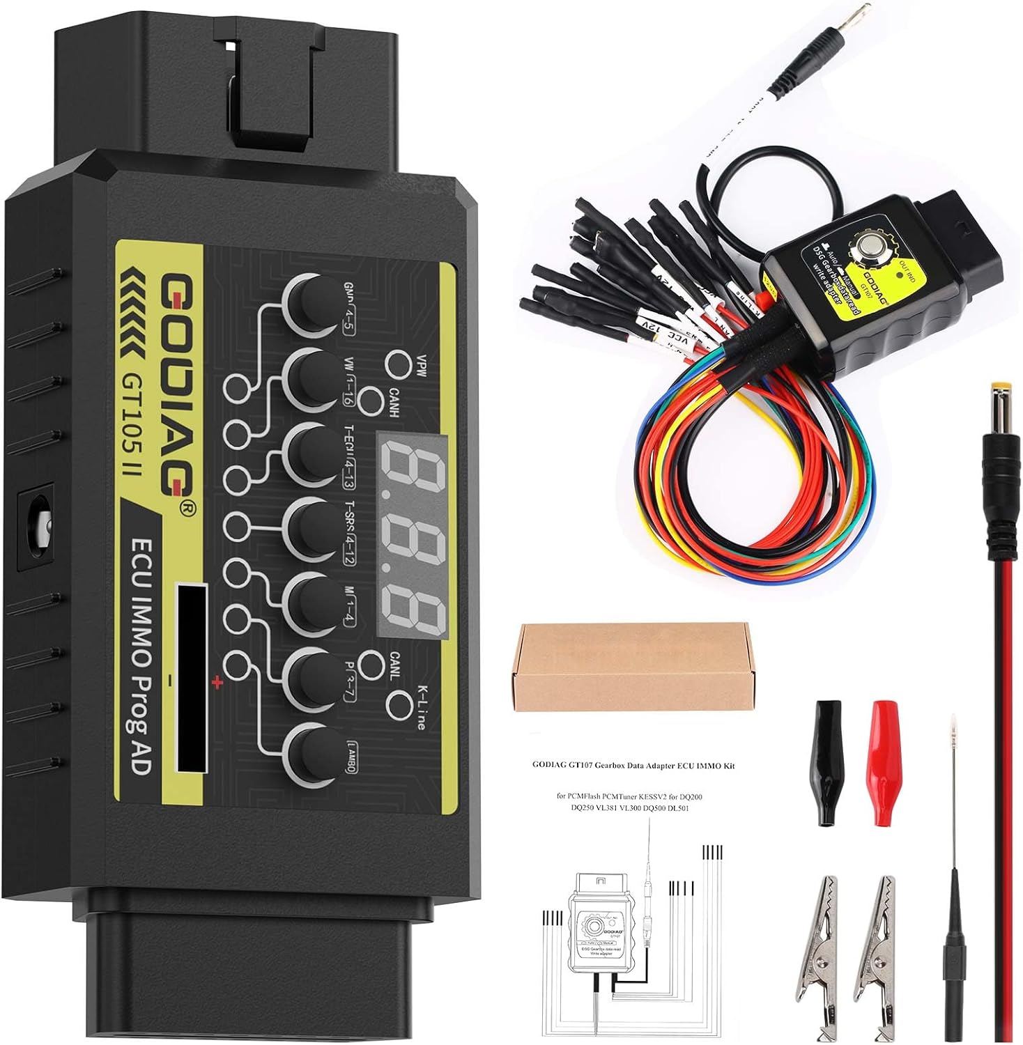
Figur 3.1: The complete GODIAG GT107 and GT105 kit, including the GT107 gearbox adapter, GT105 ECU break out box, and various connection cables and accessories.
4. Produktet er slutview
4.1 GODIAG GT107 Gear-Box Data Adapter
The GODIAG GT107 is a specialized adapter designed for direct connection to various gearbox ECUs. It facilitates reading, writing, and diagnostic operations for gearbox maintenance engineers.

Figur 4.1.1: Front view of the GODIAG GT107 Gear-Box Data Adapter, showing the "Auto/Manual" switch and "DSG Gearbox data read write adapter" label.

Figur 4.1.2: The GODIAG GT107 adapter connected to its multi-pin cable harness, used for direct connection to gearbox ECUs.
4.2 GODIAG GT105 ECU AD Break Out Box
The GODIAG GT105 is an ECU connection adapter used for OBD2 short-circuiting, ECU diagnosis, and providing power. It features signal communication indicators for various protocols.

Figur 4.2.1: Top view of the GODIAG GT105 ECU AD Break Out Box, displaying its digital voltage display, various connection buttons, and communication indicator LEDs.
5. Opsætning og tilslutning
5.1 Connecting the GT107 Gear-Box Data Adapter
The GT107 adapter is designed for direct connection to specific gearbox ECUs. Refer to the pinout diagrams below for correct wiring configurations for different gearbox models.
- Identify the specific gearbox ECU model (e.g., DQ250, DQ200, VL381, VL300, DQ500, DL501).
- Consult the relevant pinout diagram to match the GT107's cable connections to the ECU's pins.
- Ensure all connections are secure and correct before proceeding with any operations. Incorrect wiring can damage the ECU or the adapter.

Figur 5.1.1: Pinout diagram illustrating connections for DQ200 (0AM, 0CW), DQ250 (02E, 0D9), VL381 (0AW), and DQ500 (0BT, 0BH) gearbox ECUs with the GODIAG GT107.

Figur 5.1.2: Pinout diagram showing connections for V30 (01J) and VL300 (01J) gearbox ECUs, including an example of a Hytronic VL300 connection point.

Figur 5.1.3: Pinout diagram detailing connections for DL382 (0CK), DL501 (0B5), DC0/DC4 Gen2 (Renault), and LuK-UDCT (Honda) gearbox ECUs.
5.2 Connecting the GT105 ECU AD Break Out Box
The GT105 can be used for various purposes, including OBD2 short-circuiting, ECU diagnosis, and providing external power. It connects to the vehicle's OBD2 port or directly to the ECU via its breakout cables.
- For OBD2 short-circuiting or diagnosis, connect the GT105 to the vehicle's OBD2 port.
- For direct ECU connection, use the provided breakout cables to connect to the ECU's pins, ensuring correct pin assignments for power, ground, and communication lines.
- The GT105 can draw power from the vehicle's battery for outdoor maintenance by connecting the appropriate power cables.
6. Betjeningsvejledning
6.1 Using the GODIAG GT107 Gear-Box Data Adapter
The GT107 features an analog ignition switch with two modes:
- Automatisk tilstand: Kontakten er ikke trykket ned.
- Manuel tilstand: The switch is pressed down.
Vigtig: When performing data reading or writing operations, ensure you select the corresponding mode (Auto or Manual) within your diagnostic or programming software (e.g., PCMFlash, PCMTuner, Kessv2) to match the GT107's switch setting. Mismatched modes can lead to communication errors or failed operations.
6.2 Interpreting GT105 Communication Indicators
The GT105 is equipped with LED indicators for various communication protocols. These indicators help in verifying communication status:
- PWM+ (PIN2): Indicates Pulse Width Modulation communication activity.
- CANH (PIN6): Indicates CAN High communication activity.
- CANL (PIN14): Indicates CAN Low communication activity.
- K-line (PIN7): Indicates K-line communication activity.
When data communication occurs on a specific protocol, the corresponding indicator LED will flash. This allows you to quickly determine if the diagnostic or programming device is successfully communicating with the ECU.
7. Specifikationer
| Feature | Specifikation |
|---|---|
| Mærke | GODIAG |
| Model | GT107-05 |
| Strømkilde | Elektrisk med ledning |
| Operating System (GT105 related) | Android (Note: Refers to compatible diagnostic software platforms) |
| Automotive Fit Type | Køretøjsspecifik pasform |
| Varens vægt | 7.8 ounce |
| Pakkedimensioner | 8.6 x 4.3 x 1.5 tommer |
| UPC | 889327099375 |
8. Fejlfinding
- Ingen kommunikation:
- Verify all cable connections are secure and correctly matched to the ECU pinout.
- Check the GT107's Auto/Manual switch setting matches the software's selected mode.
- Observe the GT105's communication indicator LEDs. If no LEDs flash, there might be an issue with power supply or the ECU itself.
- Ensure the diagnostic/programming software is correctly configured and compatible with the specific ECU.
- Strømproblemer:
- Confirm the vehicle battery has sufficient voltage.
- Check all power supply connections to the GT105.
- Softwarefejl:
- Refer to the specific diagnostic or programming software's user manual for error code explanations.
- Sørg for, at softwaren er opdateret.
9. Vedligeholdelse
- Hold enhederne rene og fri for støv og snavs. Brug en blød, tør klud til rengøring.
- Store the devices in a cool, dry place, away from direct sunlight and extreme temperatures.
- Inspect cables and connectors regularly for any signs of wear or damage. Replace damaged components immediately.
- Do not expose the devices to liquids.
10. Garanti og support
For warranty information, technical support, or service inquiries, please contact GODIAG customer support through their official channels. Keep your purchase receipt as proof of purchase for warranty claims.


