1. Introduktion
This manual provides comprehensive instructions for the installation, operation, and maintenance of your GLEDOPTO ZigBee Pro+ 5-in-1 Smart LED Controller, Model GL-C-204P. This device is designed to control various types of LED strip lights within a smart home environment, supporting multiple configurations including RGBCCT, RGBW, RGB, CCT, and Dimmer modes. It operates with a DC 12-48V input and offers a maximum total output of 15A.
2. Sikkerhedsoplysninger
- Voltage Kompatibilitet: Sørg for, at input voltage (DC 12-48V) and current of your power supply and LED strips are compatible with the controller's specifications. Exceeding the maximum total output current of 15A or 12A per channel can damage the device and connected lighting.
- Korrekt ledningsføring: Always ensure good contact between the wire and the terminal. Incorrect or loose wiring can lead to overheating or malfunction.
- Driftsmiljø: The controller is designed for indoor use within an operating temperature range of -20°C to +45°C. Avoid exposure to extreme temperatures, moisture, or corrosive environments.
- Hub-kompatibilitet: Please note that Tuya Zigbee hubs currently block third-party devices. This GLEDOPTO Zigbee product may not connect to Tuya hubs. Verify compatibility with your specific Zigbee hub before purchase and installation.
- Professionel installation: If you are unsure about any wiring procedures, consult a qualified electrician.
3. Pakkens indhold
- 1 x GLEDOPTO ZigBee Pro+ LED Strip Controller (Model GL-C-204P)
4. Produktet er slutview
The GLEDOPTO ZigBee Pro+ controller offers versatile control for various LED strip types. Its compact design integrates essential functions for smart lighting systems.

Billede 4.1: Forside view of the GLEDOPTO ZigBee Pro+ 5-in-1 Smart LED Controller.
Nøglefunktioner:
- Høj udgangsstrøm: Total output current of 15A maximum, with a maximum of 12A per single channel, allowing for longer LED strip installations (e.g., 10-15 meters).
- Wide Voltage Område: Supports DC 12-48V input, compatible with a broad range of LED strips and panel lights.
- 5-i-1 funktionalitet: Configurable for RGBCCT, RGBW, RGB, CCT, or Dimmer LED strip types.
- Power-on Status Memory: Retains the last power-on state (on/off) or defaults to 'on' after a power interruption.
- Selectable PWM Frequency: Offers frequencies of 600Hz, 800Hz, 1000Hz, 2000Hz, 4000Hz, and 8000Hz to match various power supplies and reduce potential noise. Default frequency is 1000Hz.
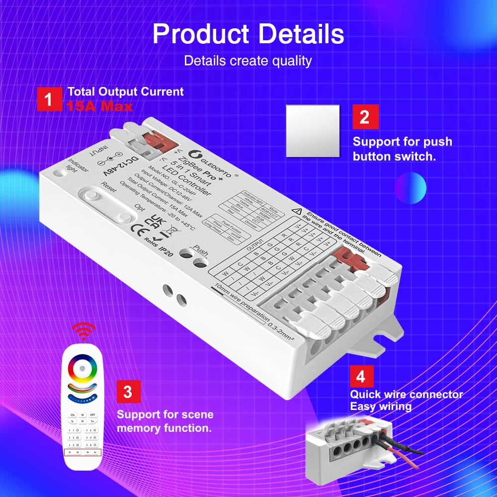
Billede 4.2: Detaljeret view of the controller highlighting its 15A maximum output, support for external push button switches, and quick wire connectors for easy wiring.
Komponenter:

Image 4.3: Diagram illustrating the key functions and components of the controller.
- Nulstil knap: Used for switching PWM frequency (short press) or resetting the controller (long press for 5 seconds).
- OPT Button: Used for switching the current device function/mode (short press) or setting power-on status (long press for 5 seconds).
- Push Button Terminal: Connects to an external push button for power on/off (short press) and brightness adjustment (long press).
- Indikatorlys: Displays different colors corresponding to the selected function mode.
5. Opsætning
5.1 Ledningsinstruktioner
The controller features quick-connect terminals for simplified wiring. Follow these steps for secure connections:
- Forbered ledninger: Strip approximately 10mm of insulation from the ends of your LED strip wires and power supply wires. The suggested wire type is 0.3-2mm² (22-14AWG).
- Åbn Connector: Gently open the connector lever upwards.
- Indsæt ledning: Insert the prepared wire into the appropriate terminal. Refer to the terminal labels for correct polarity and channel assignment (V+, R, G, B, W, C, V-).
- Sikker forbindelse: Press the connector lever down to secure the wire. Give each wire a gentle tug to ensure it is firmly held.

Image 5.1: Step-by-step guide for using the quick connect port design for wiring.
5.2 Pairing with a ZigBee Hub
This controller requires a compatible ZigBee hub for smart control. The pairing process typically involves:
- Tænd: Connect the controller to a suitable DC 12-48V power supply.
- Start parringstilstand: Consult your ZigBee hub's instructions to put it into pairing mode.
- Reset Controller: Short press the 'Reset' button on the controller or power cycle the controller (turn off and on) to initiate pairing. The indicator light may flash to confirm pairing mode.
- Bekræft parring: Once successfully paired, the controller will appear in your ZigBee hub's device list.
Important Note: If you change the device function mode using the 'OPT' button, the controller may need to be re-paired with your ZigBee hub.
6. Betjeningsvejledning
6.1 Mode Selection (5-in-1 Functionality)
The controller supports five different LED strip configurations. Use the 'OPT' button to cycle through these modes:
- Short Press 'OPT': Switches the current device function. The indicator light will change color to reflect the selected mode:
| Indikator lys farve | Mode |
|---|---|
| Hvid | RGB+CCT |
| Gul | RGBW |
| Blå | RGB |
| Grøn | CCT |
| Rød | Lysdæmper |
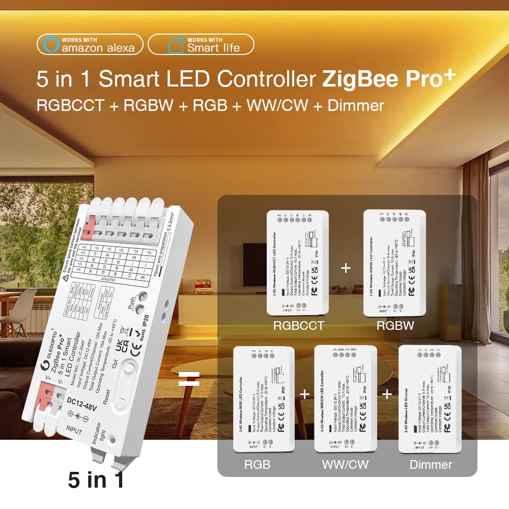
Image 6.1: Visual representation of the 5-in-1 modes supported by the controller.
6.2 Power-on Status Settings
You can configure the controller's behavior after a power interruption:
- Long Press 'OPT' (more than 5 seconds): The indicator light will flash light blue three times. This action toggles between two power-on states:
- Husk sidste stat: The controller will resume its state (on/off) prior to the power failure.
- Lights Up by Default: The controller will turn on automatically when power is restored.
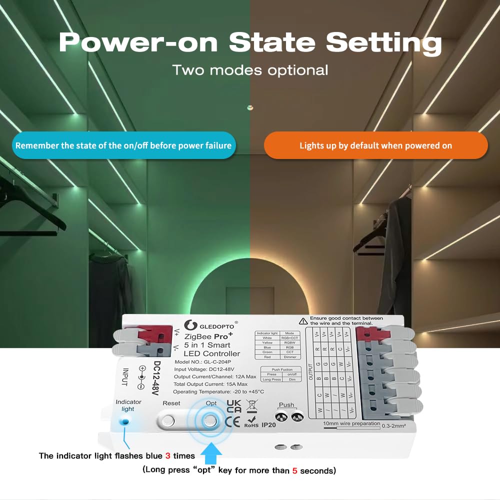
Image 6.2: Illustration of the two optional power-on state settings.
6.3 Selectable PWM Frequency
Adjusting the PWM frequency can help match different power supplies and reduce audible noise (e.g., high-pitched whine) from the LED strips or power supply.
- Short Press 'Reset': Cycles through the available frequencies. The number of flashes of the indicator light corresponds to the selected frequency:
| Blinker | Frekvens |
|---|---|
| 1 | 600 Hz |
| 2 | 800 Hz |
| 3 | 1000Hz (standard) |
| 4 | 2000 Hz |
| 5 | 4000 Hz |
| 6 | 8000 Hz |

Image 6.3: Diagram illustrating the selectable PWM frequencies and their corresponding indicator light flashes.
6.4 External Push Button Control
An external push button can be connected to the 'Push' terminals for basic control:
- Kort tryk: Toggles power On/Off.
- Langt tryk: Adjusts brightness. Release and long press again to change dimming direction (increases brightness, then decreases brightness).
7. Vedligeholdelse
- Rensning: Use a dry, soft cloth to clean the controller. Do not use harsh chemicals or abrasive cleaners.
- Miljø: Keep the controller in a dry, well-ventilated area, away from direct sunlight and sources of heat or moisture.
- Forbindelser: Periodically check all wire connections to ensure they remain secure.
8. Fejlfinding
- Controller reagerer ikke:
- Ensure the power supply is connected and providing the correct voltage (DC 12-48V).
- Check all wiring connections for looseness or incorrect polarity.
- Try power cycling the controller (disconnect and reconnect power).
- If using a ZigBee hub, ensure the controller is properly paired. Re-pair if necessary.
- LED Strips Not Lighting Up or Flickering:
- Verify that the LED strip type matches the mode selected on the controller (RGBCCT, RGBW, RGB, CCT, Dimmer).
- Check the LED strip itself for damage or incorrect wiring.
- Ensure the total current draw of the LED strips does not exceed the controller's maximum output (15A total, 12A per channel).
- If flickering occurs, try adjusting the PWM frequency using the 'Reset' button.
- High-Pitched Noise:
- This can often be resolved by changing the PWM frequency. Short press the 'Reset' button to cycle through frequencies (600Hz, 800Hz, 1000Hz, 2000Hz, 4000Hz, 8000Hz) until the noise is eliminated or reduced.
- Overophedning af controller:
- Afbryd straks strømmen.
- Check if the total current draw of the connected LED strips exceeds the controller's maximum capacity (15A total).
- Sørg for tilstrækkelig ventilation omkring controlleren.
- Verify that all wire connections are secure and not causing resistance.
- Cannot Connect to Tuya Hub:
- As stated in the safety information, Tuya Zigbee hubs may block third-party devices. This is a known compatibility issue. Consider using a different Zigbee hub (e.g., Home Assistant, Conbee) for full functionality.
9. Specifikationer
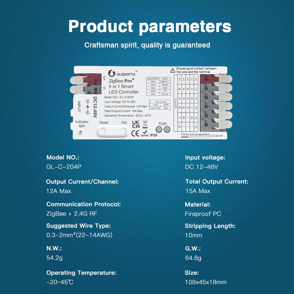
Image 9.1: Detailed product parameters for the GLEDOPTO ZigBee Pro+ LED Controller.
| Parameter | Værdi |
|---|---|
| Model nr. | GL-C-204P |
| Input bindtage | DC 12-48V |
| Udgangsstrøm/kanal | 12A Maks |
| Samlet udgangsstrøm | 15A Maks |
| Driftstemperatur | -20°C til +45°C |
| Kommunikationsprotokol | ZigBee + 2.4G RF |
| Suggested Wire Type | 0.3-2mm² (22-14AWG) |
| Stripping Længde | 10 mm |
| Materiale | Brandsikret pc |
| Nettovægt | 54.2 g |
| Bruttovægt | 64.8 g |
| Dimensioner (L x B x H) | 108 x 45 x 18 mm (4.25 x 1.77 x 0.71 tommer) |
10. Garanti og support
GLEDOPTO products are designed for reliability and performance. For warranty information and technical support, please refer to the official GLEDOPTO webwebstedet eller kontakt deres kundeservice direkte. Gem din købskvittering som købsbevis i tilfælde af garantikrav.


