1. Introduktion
This manual provides detailed instructions for assembling, operating, and maintaining your ICSTATION Electromagnetic Swing Soldering Practice Kit. This kit is designed to offer a hands-on learning experience in electronics and electromagnetism through a fun and engaging soldering project.
1.1 Design Principle
The electromagnetic swing kit operates on the fundamental principles of electromagnetic induction, showcasing the properties of Hall effect sensors. As the magnetic field varies, it generates forces that propel the swing back and forth, creating a continuous motion. This kit serves as a demonstration of electromagnetic induction, offering a practical way to explore core concepts in physics.
The whimsical PCB design features a cartoon tree and a playful dog on a swing, transforming the soldering process into an enjoyable experience. Once assembled, the project resembles an adorable scene of a dog swinging on a tree.
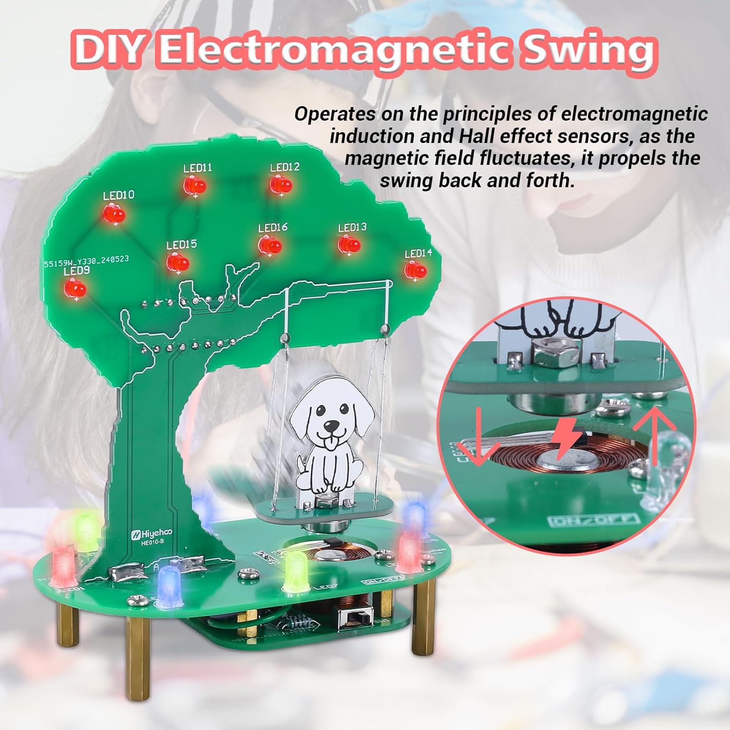
Image: Diagram showing the electromagnetic induction principle with the coil and Hall effect sensor.
1.2 STEM Practice
Beyond its visual appeal, this electromagnetic swing is a tool for STEM education. It provides an opportunity to explore the principles of electromagnetism, offering students a concrete and engaging way to grasp complex scientific concepts. Experimenting with the swing helps learners develop practical insights into physics and electronics, fostering curiosity, creativity, and critical thinking skills.

Image: The kit being used in an educational setting, demonstrating soldering practice, and the final product.
2. Komponenter og pakkeliste
Before beginning assembly, verify that all components listed below are present in your kit. The kit includes all necessary electronic components and hardware for assembly.

Image: All individual components of the soldering kit, including PCBs, wires, LEDs, resistors, and hardware.
2.1 Kit Contents Overview
- Main PCB (Tree-shaped)
- Base PCB
- Styr PCB
- USB strømkabel
- Various Resistors
- RGB LEDs and Red LEDs
- Transistors and Diodes
- Kondensatorer
- Elektromagnetisk spole
- Hall-effekt-sensor
- Tænd/sluk-knap
- Light Brightness Adjustment Knob
- Dog figure and swing wires
- Monteringsudstyr (skruer, afstandsstykker)
- Practice soldering board
3. Opsætning og montering
Assembly of this kit requires basic soldering skills. It is recommended for individuals aged 15 years and up. A practice soldering board is included to help beginners familiarize themselves with the process.
3.1 Nødvendige værktøjer (ikke inkluderet)
- Soldering Iron with a fine tip
- Solder wire (small diameter recommended)
- Solder flux (optional, but recommended for beginners)
- Wire cutters/flush cutters
- Nåle-næsetang
- Lille stjerneskruetrækker
- Sikkerhedsbriller
3.2 Monteringstrin
- Forbered dit arbejdsområde: Ensure a well-ventilated area with adequate lighting. Lay out all components and tools.
- Øvelse i lodning: If you are new to soldering, use the provided practice board to hone your skills. Focus on creating clean, shiny solder joints.
- Komponentidentifikation: Carefully identify each component using the markings on the PCBs and the component list. Pay attention to polarity for diodes and LEDs.
- Loddemodstande og dioder: Begin by soldering the smallest components, such as resistors and diodes, onto the PCBs. Ensure correct orientation for diodes.
- Lodde-LED'er: Install the RGB LEDs on the baseplate and the red LEDs on the tree PCB. Note the longer lead of an LED indicates the anode (+) and should match the PCB marking.
- Install Transistors and Capacitors: Solder these components, observing polarity for electrolytic capacitors.
- Mount the Electromagnetic Coil and Hall Sensor: Carefully solder the electromagnetic coil and the Hall effect sensor onto the base PCB. Ensure the Hall effect sensor is positioned correctly for optimal swing operation.
- Solder the On/Off Switch and Brightness Knob: Attach these control components to their designated spots on the base PCB.
- Assemble the PCBs: Connect the tree PCB to the base PCB using the provided standoffs and screws.
- Attach the Dog Figure and Swing: Secure the dog figure to the swing wires and attach the swing mechanism to the tree structure.
- Endelige forbindelser: Double-check all solder joints for continuity and ensure there are no short circuits.
4. Betjeningsvejledning
Once assembled, your electromagnetic swing is ready for operation.
4.1 Tænd
- Connect the provided USB power cable to the power port on the base PCB.
- Sæt den anden ende af USB-kablet i en kompatibel USB-strømkilde (f.eks. en computers USB-port eller en USB-vægadapter).
- Flip the On/Off switch located on the base PCB to the 'On' position.
4.2 RGB LED-lys
The kit features both static and dynamic lighting:
- The red LEDs on the tree PCB provide static illumination, resembling apples.
- The RGB LEDs on the baseplate offer dynamic lighting effects.
The brightness of the baseplate lights can be adjusted using the convenient knob located on the base PCB. Rotate the knob clockwise to increase brightness and counter-clockwise to decrease it.

Image: The RGB LED lights in operation, showing their appearance in different ambient light conditions.
4.3 Swing Operation
Once powered on, the electromagnetic induction system will activate, causing the dog figure on the swing to move back and forth. The Hall effect sensor detects the position of the swing, and the electromagnetic coil provides the necessary force to maintain continuous motion.
5. Vedligeholdelse
To ensure the longevity and proper functioning of your electromagnetic swing kit, follow these maintenance guidelines:
- Rensning: Gently wipe the PCBs and components with a dry, soft cloth to remove dust. Avoid using liquids or abrasive cleaners.
- Opbevaring: When not in use, store the kit in a dry, cool place away from direct sunlight and excessive humidity.
- Håndtering: Handle the assembled kit with care to avoid bending or damaging the swing mechanism or electronic components.
- Strømkilde: Always use a stable USB power source. Disconnect power when the kit is not in use.
6. Fejlfinding
If you encounter issues with your electromagnetic swing kit, refer to the following troubleshooting steps:
- Swing Does Not Move:
- Check all solder joints for cold joints or bridges. Re-solder any problematic connections.
- Ensure the Hall effect sensor is correctly oriented and soldered. Incorrect orientation can prevent detection.
- Verify the electromagnetic coil is properly connected and not damaged.
- Confirm the On/Off switch is in the 'On' position.
- Test the power supply and USB cable.
- Lights Do Not Illuminate:
- Check the polarity of all LEDs. LEDs are diodes and will only light up if current flows in the correct direction.
- Inspect solder joints for LEDs.
- For dynamic baseplate lights, ensure the brightness knob is not turned all the way down.
- Intermitterende drift:
- Loose connections or poor solder joints can cause intermittent issues. Re-inspect all connections.
- Ensure the swing mechanism moves freely without obstruction.
7. Specifikationer
| Feature | Detalje |
|---|---|
| Modelnummer | GY21444-1 |
| Produktdimensioner | 3.1 x 1.8 x 0.75 tommer (samlet) |
| Varens vægt | 5.3 ounce |
| Anbefalet alder | 15 år og opefter |
| Strømindgang | USB (5V DC) |

Image: Dimensions of the assembled ICSTATION Electromagnetic Swing Soldering Practice Kit.
8. Sikkerhedsoplysninger
No specific safety warnings are applicable beyond general electronics assembly precautions. Always exercise caution when working with soldering irons, as they operate at high temperatures. Ensure proper ventilation to avoid inhaling solder fumes. Keep small components away from young children to prevent choking hazards.
9. Garanti og support
For warranty information or technical support, please contact the manufacturer, ICSTATION, directly through their official channels or the retailer where the product was purchased. Please have your model number (GY21444-1) and purchase details ready when contacting support.


