1. Introduktion
Thank you for choosing the MASTECH MY75 Digital Multimeter. This device is a professional, handheld instrument designed for accurate measurement of AC/DC voltage, AC/DC current, resistance, capacitance, frequency, diode, continuity, and transistor hFE. Please read this manual thoroughly before use to ensure safe and proper operation.
1.1 Sikkerhedsoplysninger
Overhold altid sikkerhedsforanstaltningerne, når du bruger elektrisk testudstyr. Undladelse af at gøre dette kan resultere i personskade eller beskadigelse af måleren eller det udstyr, der testes.
- Do not exceed the maximum input values specified for each range.
- Udvis ekstrem forsigtighed, når du arbejder med voltages over 60V DC eller 30V AC RMS.
- Ensure the test leads are in good condition and properly connected.
- Do not operate the meter if it appears damaged or if the case is open.
- Udskift batterierne, når indikatoren for lavt batteri vises, for at sikre nøjagtige aflæsninger.
- This meter is rated CAT III 600V.
2. Produktet er slutview
The MASTECH MY75 is a compact and versatile digital multimeter suitable for domestic, industrial, and electronics applications.
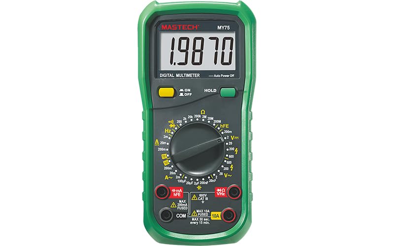
Figur 2.1: Forside view of the MASTECH MY75 Digital Multimeter, showing the LCD display, rotary switch, function buttons, and input jacks.
2.1 Hovedkomponenter
- LCD-skærm: 20000 counts display for clear readings.
- Drejekontakt: Used to select measurement functions and ranges.
- Funktionsknapper: Includes ON/OFF, HOLD, and other specific function buttons.
- Indgangsstik: Terminals for connecting test leads (COM, VΩHz, 10A, mA/µA/hFE).

Figur 2.2: Overview of MY75 features, main applications (domestic, industrial, electronics), and package contents.
3. Opsætning
3.1 Pakkens indhold
Before starting, verify that all items are present in the package:
- MASTECH MY75 digitalt multimeter
- Testledninger (røde og sorte)
- Multi-function Socket (for hFE testing)
- 2 x LR44 Batteries (pre-installed or included separately)
- Hurtig start guide
- Kalibreringscertifikat

Figure 3.1: The MASTECH MY75 Multimeter shown with its retail packaging and included accessories.

Figure 3.2: The MASTECH MY75 Multimeter with its essential accessories: test leads, LR44 batteries, and the multi-function hFE socket.
3.2 Batteriinstallation
The MASTECH MY75 uses 2 LR44 batteries. If the low battery indicator appears on the display, replace the batteries immediately to maintain measurement accuracy.
- Turn off the multimeter and disconnect all test leads.
- Find batteridækslet på bagsiden af enheden.
- Unscrew the retaining screw(s) and remove the cover.
- Remove the old batteries and insert new LR44 batteries, observing correct polarity.
- Replace the battery compartment cover and secure it with the screw(s).
3.3 Tilslutning af testledninger
Always connect the black test lead to the "COM" (Common) jack. Connect the red test lead to the appropriate input jack based on the measurement function:
- VΩHz: For bindtage, Resistance, Frequency, Capacitance, Diode, and Continuity measurements.
- mA/µA/hFE: For milliampere/mikroampere current measurements and transistor hFE testing.
- 10A: For high current (up to 10A) measurements.
4. Betjeningsvejledning
To operate the multimeter, turn the rotary switch to the desired function. The meter features auto-ranging for most functions, simplifying operation.
4.1 DC Voltage Måling (V=)
- Tilslut den sorte testledning til COM-stikket og den røde testledning til VΩHz-stikket.
- Turn the rotary switch to the "V=" position.
- Connect the test leads across the DC voltage kilde, der skal måles.
- Læs bindtage -værdi på displayet.
4.2 AC Voltage Måling (V~)
- Tilslut den sorte testledning til COM-stikket og den røde testledning til VΩHz-stikket.
- Turn the rotary switch to the "V~" position.
- Tilslut testledningerne på tværs af AC-volumentage kilde, der skal måles.
- Læs bindtage -værdi på displayet.
4.3 DC Current Measurement (A= / mA= / µA=)
- Sluk for strømmen til kredsløbet.
- Tilslut den sorte testledning til COM-stikket.
- For currents up to 200mA, connect the red test lead to the mA/µA/hFE jack. For currents up to 10A, connect the red test lead to the 10A jack.
- Turn the rotary switch to the appropriate "A=", "mA=", or "µA=" position.
- Break the circuit and connect the meter in series with the load.
- Apply power to the circuit and read the current value.
4.4 AC Current Measurement (A~ / mA~ / µA~)
- Follow the same steps as DC Current Measurement, but select the appropriate "A~", "mA~", or "µA~" position on the rotary switch.
4.5 Modstandsmåling (Ω)
- Sørg for, at kredsløbet er spændingsløst, og at alle kondensatorer er afladede.
- Tilslut den sorte testledning til COM-stikket og den røde testledning til VΩHz-stikket.
- Turn the rotary switch to the "Ω" position.
- Tilslut testledningerne på tværs af den komponent, der skal måles.
- Læs modstandsværdien på displayet.
4.6 Kapacitansmåling (F)
- Sørg for, at kondensatoren er helt afladet før måling.
- Tilslut den sorte testledning til COM-stikket og den røde testledning til VΩHz-stikket.
- Turn the rotary switch to the "F" position.
- Tilslut testledningerne på tværs af kondensatorterminalerne.
- Læs kapacitansværdien på displayet.
4.7 Frequency Measurement (Hz)
- Tilslut den sorte testledning til COM-stikket og den røde testledning til VΩHz-stikket.
- Turn the rotary switch to the "Hz" position.
- Tilslut testledningerne på tværs af signalkilden.
- Aflæs frekvensværdien på displayet.
4.8 Diodetest (→|)
- Sørg for, at kredsløbet er spændingsløst.
- Tilslut den sorte testledning til COM-stikket og den røde testledning til VΩHz-stikket.
- Turn the rotary switch to the Diode symbol position.
- Connect the red lead to the anode and the black lead to the cathode of the diode. A forward voltage drop will be displayed (Diode Open Voltage 3.0V).
- Reverse the leads. The display should show "OL" (Open Loop) for a good diode.
4.9 Kontinuitetstest ())))
- Sørg for, at kredsløbet er spændingsløst.
- Tilslut den sorte testledning til COM-stikket og den røde testledning til VΩHz-stikket.
- Turn the rotary switch to the Continuity symbol position.
- Tilslut testledningerne på tværs af kredsløbet eller komponenten.
- If the resistance is less than approximately 60Ω, the buzzer will sound, indicating continuity.
4.10 Transistor hFE Test
- Connect the multi-function socket to the mA/µA/hFE and COM jacks.
- Turn the rotary switch to the "hFE" position.
- Insert the transistor's emitter, base, and collector leads into the corresponding holes on the multi-function socket (NPN or PNP).
- Read the hFE value (0-1000) on the display.
5. Funktioner
- Display 20000 Counts: Provides high resolution for precise measurements.
- Data Hold: Tryk på "HOLD"-knappen for at fryse den aktuelle aflæsning på displayet. Tryk igen for at slippe.
- Automatisk sluk: The meter automatically turns off after a period of inactivity to conserve battery life.
- Low Battery Display: An icon on the display indicates when the batteries are low and need replacement.
6. Vedligeholdelse
6.1 Rengøring
Tør sagen af med annonceamp en klud og et mildt rengøringsmiddel. Brug ikke slibemidler eller opløsningsmidler. Hold indgangsterminalerne fri for snavs og fugt.
6.2 Udskiftning af batteri
Refer to Section 3.2 for detailed instructions on replacing the LR44 batteries.
6.3 Opbevaring
If the meter is not used for an extended period, remove the batteries to prevent leakage and damage. Store the meter in a cool, dry place away from direct sunlight.
7. Fejlfinding
| Problem | Mulig årsag | Løsning |
|---|---|---|
| Ingen visning eller svag visning | Lave eller døde batterier; Forkert batteriinstallation | Udskift batterier; Kontroller batteripolariteten |
| "OL" (Overbelastning) vises | Input value exceeds selected range; Open circuit | Select a higher range; Check circuit connections |
| Forkerte aflæsninger | Low batteries; Incorrect function/range selected; Poor test lead connection | Replace batteries; Verify function/range; Ensure secure connections |
| Ingen kontinuitetsbip | Resistance too high; Open circuit | Check circuit for breaks; Ensure resistance is below 60Ω |
8. Specifikationer
The following table details the technical specifications of the MASTECH MY75 Digital Multimeter.

Figure 8.1: Detailed specifications including range, resolution, and accuracy for various measurement functions of the MY75.
| Måletype | Rækkevidde | Opløsning | Nøjagtighed |
|---|---|---|---|
| DC bindtage | 200mV / 2V / 20V / 200V / 600V | 0.01mV / 0.1mV / 1mV / 10mV / 0.1V / 1V | ±(0.05%+3) til ±(0.15%+3) |
| AC Voltage | 2V / 20V / 200V / 600V | 0.1mV / 1mV / 10mV / 0.1V | ±(0.5%+3) til ±(1.0%+15) |
| DC-strøm | 2mA / 20mA / 200mA / 10A | 0.1µA / 1µA / 10µA / 1mA / 10mA | ±(0.5%+50) til ±(2.0%+10) |
| AC strøm | 2mA / 20mA / 200mA / 10A | 0.1µA / 1µA / 10µA / 1mA / 10mA | ±(0.8%+50) til ±(2.5%+10) |
| Modstand | 200Ω / 2kΩ / 20kΩ / 200kΩ / 2MΩ / 20MΩ / 200MΩ | 0.01Ω / 0.1Ω / 1Ω / 10Ω / 100Ω / 1kΩ / 10kΩ | ±(0.5%+10) til ±(5.0%+10) |
| Kapacitans | 2µF / 20µF / 100µF / 20nF / 200nF | 0.1nF / 1nF / 10nF / 1pF / 10pF | ±(4.0 %+20) |
| Frekvens | 20kHz | 1 Hz | ±(1.5 %+5) |
| Diode åben volumentage | 3.0V | N/A | N/A |
| Kontinuitet Buzzer | <60Ω | N/A | N/A |
| Transistor hFE | 0~1000 | N/A | N/A |
| Vise | 20000 tæller | N/A | N/A |
| Strømkilde | 2 x LR44-batterier | N/A | N/A |
| Dimensioner (L x B x H) | 16 x 9 x 5 cm | N/A | N/A |
| Vægt | 500 g | N/A | N/A |
| Sikkerhedsvurdering | KAT III 600V | N/A | N/A |
| Certificeringer | CE, RoHS | N/A | N/A |
9. Garanti og support
MASTECH products are designed for reliability and performance. For warranty information or technical support, please refer to the contact details provided with your purchase documentation or visit the official MASTECH webwebsted. Behold din købskvittering som købsbevis i tilfælde af garantikrav.
EU-reservedeles tilgængelighedsvarighed: 1 år.


