Indledning
This manual provides detailed instructions for the installation, setup, and operation of your QIACHIP Mini Wireless Remote Control Switch. This device is designed for various applications requiring remote control of DC-powered systems, such as LED lights, car batteries, garage doors, and other electronic devices. Please read this manual thoroughly before use to ensure proper functionality and safety.

Image: Two QIACHIP wireless remote controls and two receiver modules, illustrating the complete product package.
Produkt overview og funktioner
The QIACHIP Mini Wireless Remote Control Switch operates on a 433 MHz frequency, offering reliable wireless control. It features a compact design and supports a wide range of DC input voltages.
- Frekvens: 433 MHz universal wireless.
- Input bindtage: DC 5.5V to 24V (some versions may support 5V to 60V).
- Arbejdstilstand: Superheterodyne for stable reception.
- Transmissionsafstand: Approximately 50-100 meters in open spaces.
- Fjernbetjeningskompatibilitet: Supports EV1527 learning code remote controls, up to 20 remotes.
- Udgangsterminaler: Normally Open (NO), Normally Closed (NC), Common (COM).
- Funktionstilstande: Momentary, Toggle, Latched, and Delay.

Image: A close-up of the receiver module highlighting the exposed antenna for improved reception and indicating a wider voltage range (5.5-24V to 5-60V) for newer versions.
Specifikationer
| Parameter | Værdi |
| Input bindtage | DC 5.5V - 24V (Some versions support DC 5V - 60V) |
| Max Relay Contact Current | 20 Amps |
| RF-frekvens | 433 MHz |
| PCB Dimensions (L x W x H) | 47 x 26 x 18 mm |
| Udgangsterminaler | NO (Normally Open), NC (Normally Closed), COM (Common) |
| Kontrolmetode | Remote Wireless |
| Fjernbetjening batteritype | 2 x CR2032 (inkluderet) |
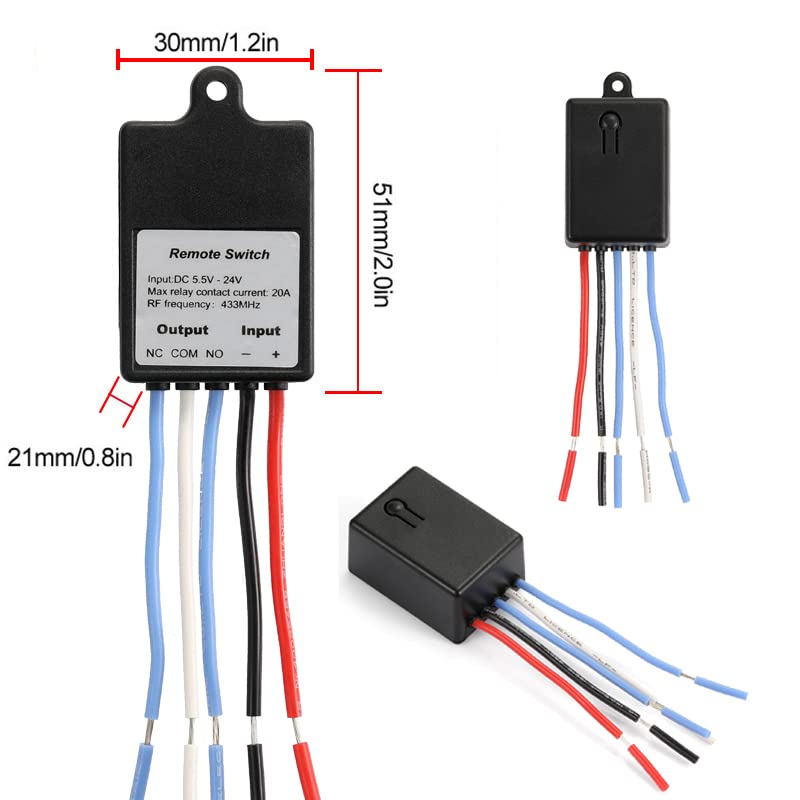
Image: Diagram showing the physical dimensions of the receiver module: 30mm (1.2in) width, 51mm (2.0in) length, and 21mm (0.8in) height for the main body.
Opsætning og ledningsføring
Komponentidentifikation
Familiarize yourself with the components of the receiver module before proceeding with wiring.

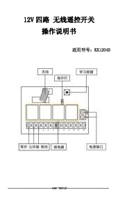
Billede: Et overheadbillede view of the receiver's circuit board, labeling key components such as the learning button, indicator lamp, relay, receiving module, antenna, and output terminals (NO, COM, NC), along with the DC 5.5V-24V input terminals.
Ledningsdiagrammer
Ensure all power is disconnected before attempting any wiring. Connect the receiver according to your specific application using the appropriate diagram below.

Image: Wiring diagram for connecting a DC load (e.g., an LED light) to the QIACHIP receiver. The diagram shows the DC 5.5-24V power input connected to V+ and V-, and the load connected between NO (Normally Open) and COM (Common) terminals, with the other side of the load connected to the positive power supply.

Image: Wiring diagram for an access control or door lock application. The diagram illustrates connecting the receiver to a button and a door lock, powered by a DC 5.5-24V source.

Image: Wiring diagram for controlling a load with an external power supply. This setup shows the receiver's input connected to a DC 5.5-24V source, while the load is powered by a separate 1V-250V AC/DC source, connected through the NO/COM/NC terminals of the relay.
Operating Modes and Pairing
The QIACHIP remote control switch supports four operating modes. Follow the instructions below to pair your remote control and set the desired mode.
Nulstilling af modtageren
To clear all previously paired remote controls, press the learning button on the receiver module 8 times continuously. The indicator light will flash seven times and then turn off, indicating a successful reset.

Billede: Et nærbillede view of the QIACHIP receiver module, clearly indicating the location of the learning button.
Pairing and Mode Selection
1. Momentary Mode
In Momentary mode, the relay activates only while the remote button is pressed. Releasing the button deactivates the relay.
- Press the learning button on the module 1 gang. Indikatorlyset vil tænde.
- Press the desired button on the remote control. The indicator light will flash 3 times and then turn off.
- Pairing is successful. If no code is received within 15 seconds, the indicator light will turn off, exiting the learning state.

Image: Diagram showing Momentary mode: Press and hold button A to turn ON, release button A to turn OFF.
2. Skift tilstand
In Toggle mode, each press of the remote button alternates the relay state (ON/OFF).
- Press the learning button on the module 2 gange. Indikatorlyset vil tænde.
- Press the desired button on the remote control. The indicator light will flash 3 times and then turn off.
- Pairing is successful. If no code is received within 15 seconds, the indicator light will turn off, exiting the learning state.

Image: Diagram showing Toggle mode: Press button A to turn ON, press button A again to turn OFF.
3. Latched Mode
In Latched mode, one button turns the relay ON, and another button turns it OFF. This requires a remote with at least two buttons (e.g., A and B).
- Press the learning button on the receiver 3 gange. Indikatorlyset vil tænde.
- Press the first button (e.g., 'A') on the remote control. The indicator light will flash and then stay on.
- Press the second button (e.g., 'B') on the remote control. The indicator light will turn off.
- Parringen er vellykket.

Image: Diagram showing Latched mode: Press button A to turn ON, press button B to turn OFF.
4. Delay Mode
In Delay mode, the relay activates for a set duration after the remote button is pressed, then automatically turns off.
- Press the learning button on the receiver a specific number of times for the desired delay:
- 4 gange: 5 sekunders forsinkelse
- 5 gange: 10 sekunders forsinkelse
- 6 gange: 15 sekunders forsinkelse
- 7 gange: 20 sekunders forsinkelse
- Press the desired button on the remote control. The indicator light will turn off after successful pairing.
- The relay will activate for the set delay time after the remote button is pressed.

Image: Diagram showing Delay mode: Press button A to start countdown, then automatically OFF after 5s/10s/15s (depending on setting).
Opretholdelse
- Rensning: Use a dry, soft cloth to clean the receiver and remote control. Avoid using liquids or abrasive cleaners.
- Udskiftning af batteri: The remote control uses two CR2032 batteries. If the remote's range decreases significantly or it stops responding, replace the batteries. Ensure correct polarity when inserting new batteries.
- Antenne: For optimal reception, ensure the receiver's antenna is not obstructed. If reception is poor, consider extending the internal antenna outside the receiver casing if possible, as shown in some product images.
- Opbevaring: Opbevar enheden et køligt, tørt sted væk fra direkte sollys og ekstreme temperaturer.
Fejlfinding
| Problem | Mulig årsag | Løsning |
| Modtageren reagerer ikke på fjernbetjeningen. |
|
|
| Kort rækkevidde for fjernbetjening. |
|
|
| Relay does not switch or load does not activate. |
|
|

Image: An overhead floor plan illustrating the typical remote control range of 50-100 meters, showing how the signal can travel through walls but is optimized in open spaces.
Garanti og support
For warranty information or technical support, please refer to the product's purchase platform or contact QIACHIP customer service directly. Keep your purchase receipt for warranty claims.
Fabrikant: QIACHIP