Indledning
This manual provides comprehensive instructions for the setup, operation, and maintenance of your Radiolink AT10II 12 Channels RC Transmitter and its accompanying components, including the R12DS Receiver, Crossflight Flight Controller, and M8N TS100 GPS Compass Module. Please read this manual thoroughly before using the product to ensure safe and optimal performance.
Produkt overview
The Radiolink AT10II is a versatile 12-channel radio control system designed for a wide range of RC models, including planes, multi-copters, helicopters, cars, and boats. It features advanced telemetry capabilities, programmable mix controls, and robust signal transmission.
Komponenter inkluderet:
- Radiolink AT10II Radio Transmitter
- Radiolink R12DS Radio Receiver
- Radiolink Crossflight Flight Controller
- Radiolink M8N TS100 GPS Compass Module
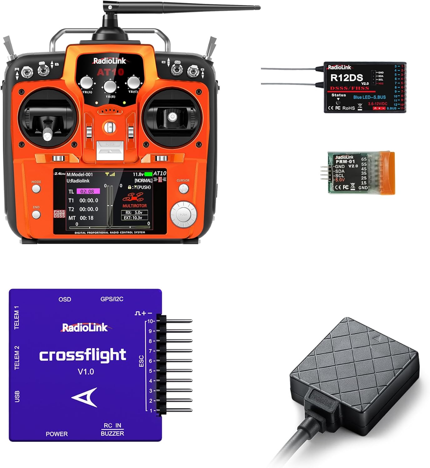
Figur 1: Overview of the Radiolink AT10II RC system, including the transmitter, R12DS receiver, Crossflight flight controller, and M8N TS100 GPS module.

Figure 2: The AT10II transmitter shown alongside the R12DS receiver and the PRM-01 telemetry module, illustrating the core radio components.
Nøglefunktioner:
- 12 kanaler: Giver omfattende kontrolmuligheder for komplekse modeller.
- Telemetri: Includes Battery Voltage Telemetry and RSSI (Received Signal Strength Indicator) for real-time flight information.
- Tilpasning: Features Dual/Triple Rates, End Point Adjustment, Switch Customization, and Channels Mix Control.
- Kompatibilitet: Adapts to a wide range of airplanes, helicopters, quadcopters, cars, and boats, with 15 model storage memory.
- Crossflight Flight Controller: New layout similar to PIXHAWK, with 10 PWM outputs and integrated OSD module. Supports up to 2617 waypoints for multi-copters and 2623 for airplanes, cars, and boats.
- High Positioning Accuracy: M8N TS100 GPS Compass Module offers approximately 50 centimeters positioning accuracy, capable of acquiring 20 satellites within seconds in open ground.
- Sikkerhedsfunktioner: Includes Fail-safe Setting and Reverse Polarity Protection.

Figure 3: Visual representation of key features including 12 channels, 15 models storage, model's voltage telemetry, long range control, programmable mix control, and crossfire module support.
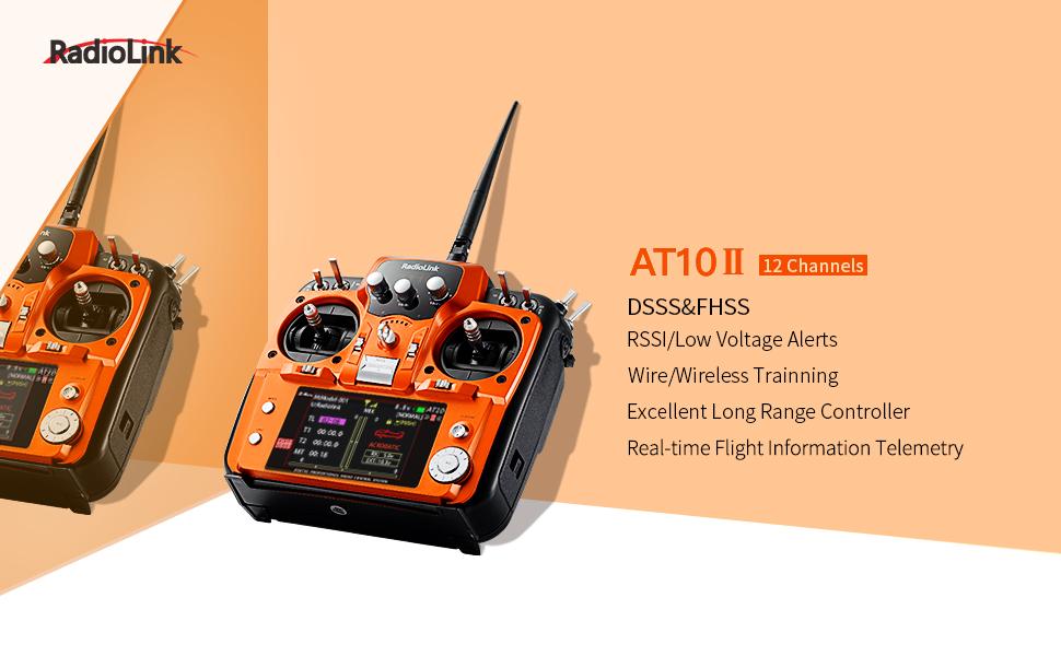
Figure 4: Highlights of the AT10II's DSSS/FHSS technology, including RSSI/Low Voltage Alerts, Wire/Wireless Training, Excellent Long Range Control, and Real-time Flight Information Telemetry.
Opsætningsvejledning
1. Strømforsyning til senderen
The AT10II transmitter supports 8 AA batteries or a 2S-4S LiPo battery. Ensure correct polarity when inserting batteries.

Figure 5: Illustration of the battery compartment, showing compatibility with 8 AA batteries or a 2S-4S LiPo battery. Battery box dimensions are 115(L)x32(W)x30.5(H)mm (4.5"x1.25"x1.2").
2. Receiver Connection (R12DS)
The R12DS receiver supports two signal output modes: PWM-Red and SBUS-Blue. Connect your servos and other components according to the chosen mode.

Figure 6: Detailed diagram of the R12DS receiver showing pinouts for both PWM (Red LED) and SBUS (Blue LED) signal output modes. The binding button is also indicated.

Figur 7: Nærbillede view illustrating the R12DS receiver's PWM-Red and SBUS-Blue signal work modes, indicating the corresponding LED colors.
3. Crossflight Flight Controller Connections
The Crossflight flight controller integrates various ports for comprehensive control and data acquisition. Ensure all connections are secure and correctly oriented.

Figure 8: Diagram detailing the connectors and protocols of the Crossflight flight controller, including ports for image transmission, camera, GPS/ultrasonic sensor, data transmission (Mavlink UART and CRSF), USB, power module, and main PWM/ESC/Servo outputs.
4. Wiring Diagram Example
Below is a typical wiring setup for an airplane using the R12DS receiver and PRM-01 telemetry module.

Figure 9: A wiring diagram illustrating the connection of the R12DS receiver, PRM-01 telemetry module, ESC (Electric Speed Control), and airplane battery.
5. Flight Mode Setup (Crossflight)
Setting up flight modes is crucial for controlling your model's behavior. This process involves selecting modes in the Mission Planner software and configuring the transmitter switches.
Video 1: This video demonstrates how to set flight modes using the Mission Planner software and configure the Radiolink AT10II transmitter. It shows selecting flight modes 1-6, saving them, and then adjusting channel settings (CH1-0%, CH2-25%, CH3-40%, CH4-60%, CH5-75%, CH6-100%) on the transmitter. The video also illustrates toggling SwC and SwD switches to change flight modes, with the chosen mode turning green in Mission Planner.
For detailed setup, use Radiolink Mission Planner, ArduPilot Mission Planner, or QGC Mission Planner. Note that Crossflight firmware can only be upgraded via Radiolink Mission Planner.

Figure 10: This image highlights the AT10II's support for simulator/trainer and Crossfire modules, along with its firmware update capability via a USB port (not for charging).
Betjeningsvejledning
Telemetry Monitoring
The AT10II provides real-time telemetry data, including battery voltage and RSSI, displayed on the transmitter screen. This allows for continuous monitoring of critical flight parameters.

Figure 11: Display screens of the AT10II showing Voltage Telemetry Monitor, Programmable Mix Control (8 Groups), Friendly Remind Sounds/Words (e.g., RSSI ALARM!), and Channel's Servo Travel Display.
Throttle Mode Adjustment
The AT10II supports changing the throttle stick from left to right or setting a dual-stick back-to-center configuration, accommodating various pilot preferences and model types.

Figure 12: Illustrates the flexibility of the AT10II to support Left Throttle (Mode 2), Dual-stick Back to Center, and Right Throttle (Mode 1) configurations, with usage recommendations for different model types.
GPS -funktionalitet
The M8N TS100 GPS Compass Module enables advanced features such as GPS Auto Return and Custom Flight Path programming, enhancing flight safety and versatility.

Figure 13: Diagram showing GPS Auto Return and Custom Flight Path capabilities with the TS100 GPS module, highlighting its 50cm positioning accuracy and waypoint navigation.
Model Versatility
The Radiolink AT10II system is highly adaptable, supporting a wide array of RC models from multi-rotors and airplanes to helicopters, cars, and boats.

Figure 14: The AT10II transmitter in use, surrounded by images of various RC models it can control, including airplanes, multi-rotors, and trucks.

Figure 15: The Crossflight Flight Controller is shown with examples of models it is adaptable to, such as 3-8 copters, planes, rovers, boats/submarines, helicopters, and antenna trackers.
Opretholdelse
To ensure the longevity and reliable operation of your Radiolink AT10II system, follow these maintenance guidelines:
- Hold sender og modtager rene og fri for støv og snavs. Brug en blød, tør klud til rengøring.
- Avoid exposing the components to extreme temperatures, humidity, or direct sunlight.
- Regularly check all wiring and connectors for signs of wear or damage. Replace any damaged parts immediately.
- Ensure the antenna is securely attached and undamaged. The 7dBi high gain antenna is designed for optimal signal reception.
- When not in use for extended periods, remove batteries from the transmitter to prevent leakage.
- Store the system in a dry, cool place, preferably in its original packaging or a protective case.

Figure 16: Image showing the 7dBi High Gain Antenna, emphasizing its importance for reliable signal transmission and reception.
Fejlfinding
This section addresses common issues you might encounter with your Radiolink AT10II system.
| Problem | Mulig årsag | Løsning |
|---|---|---|
| Ingen strøm til senderen | Incorrect battery installation, low battery voltage, faulty battery. | Check battery polarity. Replace with fresh batteries or fully charged LiPo. Ensure battery contacts are clean. |
| Modtager er ikke bindende | Incorrect binding procedure, transmitter/receiver too far apart, interference. | Refer to the binding instructions in the full user manual. Ensure transmitter and receiver are close during binding. Avoid sources of interference. |
| Loss of signal/range issues | Damaged antenna, excessive distance, environmental interference, low RSSI. | Inspect antenna for damage. Operate within specified range. Avoid areas with high electromagnetic interference. Monitor RSSI telemetry. |
| Flight controller not responding | Incorrect wiring, firmware issue, calibration error. | Verify all connections to the flight controller. Check firmware version and update if necessary using Radiolink Mission Planner. Recalibrate sensors (accelerometer, compass). |
| GPS not acquiring satellites | Hindret view of sky, faulty GPS module, incorrect connection. | Operate in an open area with clear sky view. Check GPS module connection to the flight controller. Ensure the module is correctly oriented. |
For more detailed troubleshooting, please refer to the full user manual available on the Radiolink Direct store or contact customer support.
Specifikationer
| Komponent | Specifikation |
|---|---|
| Radiolink AT10II Transmitter | |
| Kanaler | 12 kanaler |
| Operation Voltage | 7.4V - 15V (8 AA batteries or 2S-4S LiPo) |
| Frekvens | 2.4GHz DSSS & FHSS |
| Telemetri | Batteri Voltage, RSSI |
| Radiolink R12DS-modtager | |
| Kanaler | 12 Channels (PWM/SBUS) |
| Operation Voltage | 3.0V - 10V DC |
| Crossflight Flight Controller | |
| PWM udgang | 10 kanaler |
| Integrerede moduler | OSD |
| M8N TS100 GPS Compass Module | |
| Positioneringsnøjagtighed | Ca. 50 cm |
| Satellite Acquisition | 20 satellites within seconds (open ground) |
| Generel | |
| Antenne | 7dBi High Gain-antenne |
| Modelopbevaring | 15 modeller |
| Vandmodstandsniveau | Vandtæt |

Figure 17: Dimensions of the Voltage Telemetry Module (PRM-01), measuring 1.3in x 0.87in x 0.37in.
Garanti og support
Radiolink Electronic Co., Ltd. is committed to providing high-quality products and excellent customer service. For any inquiries or support needs, please refer to the following:
- Garanti: Please refer to the product packaging or the official Radiolink webwebstedet for specifikke garantivilkår.
- Online support: Quick support can be found by contacting Radiolink Direct store or through the online User Instruction.
- Full User Manual & FAQ: Comprehensive user manuals and FAQ troubleshooting files are available on each Amazon sales page for Radiolink products.
Radiolink's professional research and development team, composed of RC hobbyists, continuously works to create more powerful products and ensure customer satisfaction.


