1. Introduktion
This manual provides detailed instructions for the installation, operation, and maintenance of your Powmr 60A PWM Solar Charge Controller. Please read this manual thoroughly before installation and use to ensure optimal performance and safety. This controller is designed to manage power flow from solar panels to batteries and loads in 12V, 24V, 36V, or 48V systems.
Sikkerhedsforanstaltninger
- Ensure all connections are correct and secure before applying power.
- Do not connect the solar panel array to the controller without a battery.
- Always connect the battery first, then the solar panel, and finally the load. Disconnect in reverse order.
- Avoid short-circuiting the battery terminals or solar panel terminals.
- Installer styreenheden i et godt ventileret område, væk fra brandfarlige materialer.
- The controller generates heat; ensure adequate airflow.
- Kun kvalificeret personale bør udføre installation og vedligeholdelse.
2. Produktfunktioner
- Automatisk system voltage identification: 12V, 24V, 36V, 48V.
- Maksimal PV input voltage: 100VDC.
- Maximum input power: 720W (12V), 1440W (24V), 2160W (36V), 2880W (48V).
- Compatibility with various battery types: Lithium-ion (LiFePO4, Ternary Lithium), Lead-acid (SEL, USE, FLD, GEL). Supports user-defined battery parameters.
- Built-in dual USB output (5V/2.5A max) for charging mobile devices.
- Avanceret 3-stage PWM charging technology (Bulk, Boost, Float) for efficient and safe battery charging.
- Adjustable load enable duration with solar light control and time control modes.
- Backlit LCD screen for real-time monitoring of charging current, generated energy, temperature, battery voltage og fejlkoder.
- Multiple protection features: overheating, output short circuit, over-discharging, reverse polarity connection, and maximum charging current limit.
- Natural convection cooling for silent operation.
3. Produktet er slutview og komponenter
Familiarize yourself with the components of the Powmr 60A PWM Solar Charge Controller.
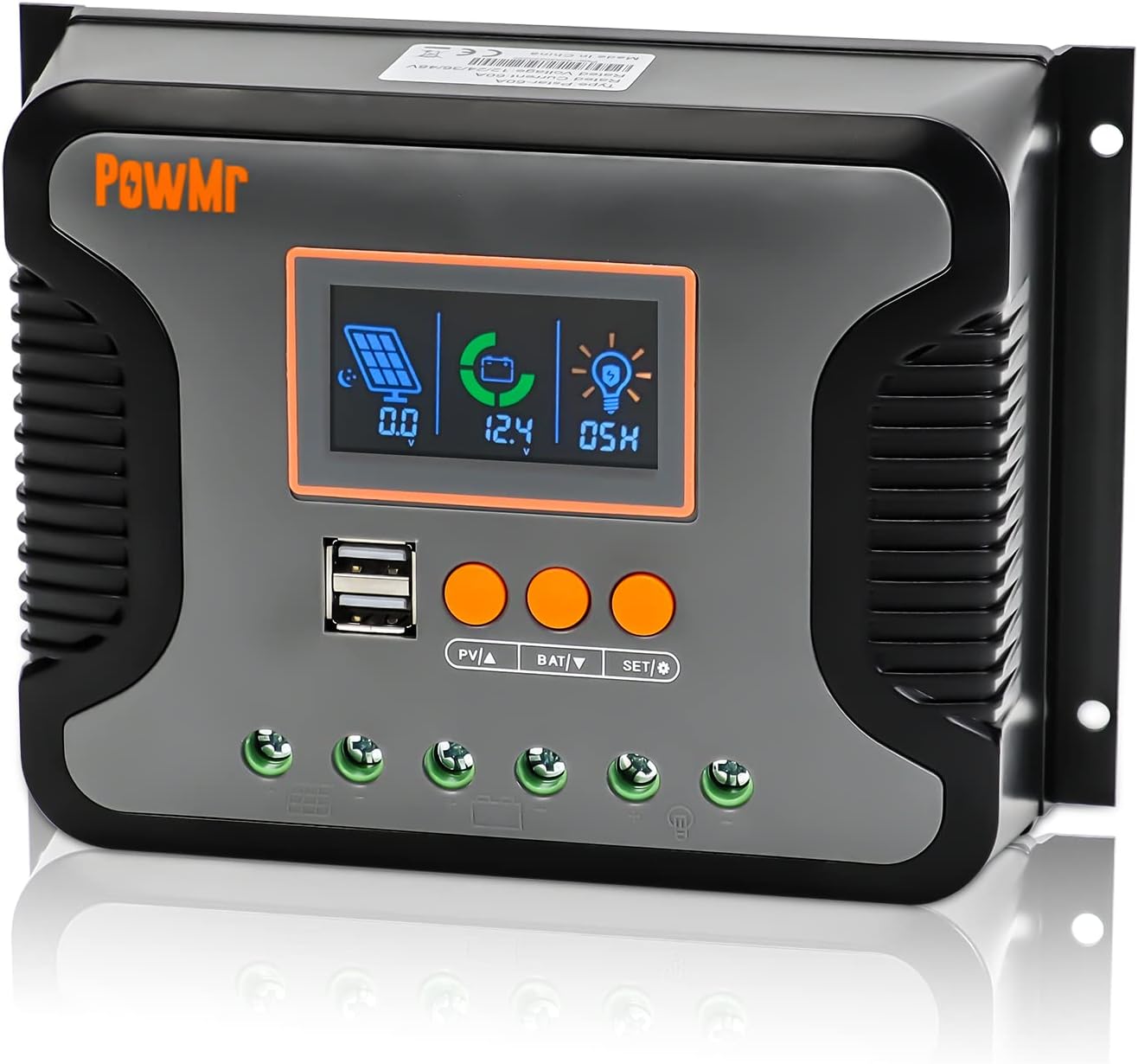
Figur 3.1: Front view of the Powmr 60A PWM Solar Charge Controller, showing the LCD display, USB ports, and control buttons.

Figur 3.2: Detailed component diagram, indicating the USB port, LCD display, function keys, mounting holes, PV input port, battery port, load port, and heat sink.
- LCD-skærm: Shows system status and parameters.
- USB-porte: Dual 5V/2.5A outputs for charging external devices.
- Funktionstaster: Used for navigation and setting parameters (PV▲, BAT▼, SET/☉).
- PV Input Port: Connects to solar panels.
- Batteriport: Tilsluttes batteribanken.
- Load Port: Connects to DC loads.
- Monteringshuller: For secure installation.
- Køleplade: Located at the back for passive cooling.
4. Opsætning og installation
Proper installation is crucial for the safe and efficient operation of the solar charge controller. Follow these steps carefully.
4.1 Ledningsdiagram

Figur 4.1: Connection diagram showing solar panels, battery, load, and optional inverter connections to the controller.
4.2 Tilslutningstrin
- Tilslut batteriet: Connect the battery to the controller's battery terminals. Ensure correct polarity (+ to + and - to -). The controller will automatically detect the system voltage (12V/24V/36V/48V).
- Tilslut solpanelerne: Connect the solar panel array to the controller's PV input terminals. Ensure correct polarity. The maximum open circuit voltage of the PV array should not exceed 100VDC.
- Tilslut belastningen: Connect the DC load to the controller's load terminals. Ensure correct polarity.
- Optional Inverter Connection: If using an inverter, connect it to the battery bank, not directly to the controller's load terminals, unless the inverter is a small DC load within the controller's load current limits.
Vigtig: Always connect the battery first, then the solar panels, and finally the load. Disconnect in the reverse order: load, then solar panels, then battery.
5. Betjeningsvejledning
The controller features an LCD screen and three function keys for monitoring and parameter adjustment.

Figur 5.1: Illustration of the LCD screen and function keys for operation.
5.1 Checking Information
- Press the "PV▲" key to cycle through PV information: PV input voltage, PV input current, and PV input power.
- Press the "BAT▼" key to cycle through battery information: current battery voltage, equipment temperature, battery calibration voltage, batteritype, boostladning voltage, flydeladning voltage, low DC cut-off recovery voltage, and low DC cut-off voltage.
5.2 Configuring Load Enable Duration
- Press and hold the "SET/☉" key to enter the load mode setting.
- 00H: Solar light control mode. The DC output is enabled when solar energy is sufficient.
- 24H: Load is turned on immediately (default setting).
- 01H-23H: Adjust the load enable duration in hours.
5.3 Battery Type Compatibility and Calibration

Figur 5.2: Visual representation of various battery types supported by the controller.
The controller supports 14 types of batteries, including various lead-acid (SEL, USE, FLD, GEL) and lithium batteries (LiFePO4, Ternary Lithium). You can select the battery type via the LCD screen. User-defined battery parameters are also supported.

Figur 5.3: Steps for calibrating battery voltage ved hjælp af et multimeter.
To calibrate battery voltage:
- Navigate to the "battery calibration voltage" item using the "BAT▼" key. Press and hold "BAT▼" to enter the setting.
- Use the "PV▲" or "BAT▼" keys to adjust the displayed voltage to match the actual battery voltage measured by a multimeter.
- Press "SET/☉" to confirm and save the calibration.
6. Opladningstilstande
The controller utilizes a 3-stage PWM charging algorithm to optimize battery life and performance.

Figur 6.1: Diagram illustrating the Bulk, Boost, and Float charging stages.
- Bulkafgift: The battery is charged at maximum current until its voltage reaches the configured boost charging voltage.
- Boost Charge: The battery continues charging at the configured boost voltage. The current gradually decreases as the battery approaches full charge.
- Flydeafgift: Once the battery is fully charged, the controller reduces the charging voltage and current to maintain the battery at a floating voltage, preventing overcharging.
- Return to Bulk: If the load draws excessive power and the battery voltage drops below a certain threshold, the controller will return to the Bulk charge stage.
7. Flere beskyttelser
The Powmr 60A PWM Solar Charge Controller incorporates several safety features to protect the system and connected devices.

Figur 7.1: Visual representation of the controller's comprehensive protection mechanisms.
- Reverse Polarity Connection Protection: Prevents damage if battery or solar panel connections are reversed.
- Beskyttelse mod overafladning: Disconnects the load to prevent deep discharge of the battery.
- Overophedningsbeskyttelse: Automatically stops charging if the controller's internal temperature exceeds safe limits.
- Udgangskortslutningsbeskyttelse: Protects against damage from short circuits on the load output.
- Maximum Charging Current Limit Protection: Regulates the charging current to prevent overcurrent to the battery.
8. Vedligeholdelse
Regular maintenance ensures the longevity and optimal performance of your solar charge controller.
- Renhed: Hold controlleren ren og fri for støv og snavs. Brug en tør klud til rengøring.
- Forbindelser: Periodically check all wiring connections for tightness and corrosion. Loose connections can cause overheating and damage.
- Ventilation: Ensure the installation area remains well-ventilated to allow for proper heat dissipation. Do not obstruct the heat sink.
- Batteriinspektion: Regularly inspect your batteries for any signs of damage, corrosion, or leakage. Follow battery manufacturer's maintenance guidelines.
- Parameter Check: Af og til vedrview the controller's display to ensure parameters are set correctly and the system is operating as expected.
9. Fejlfinding
This section addresses common issues you might encounter with your solar charge controller.
| Problem | Mulig årsag | Løsning |
|---|---|---|
| No display/Controller not powering on | Batteri ikke tilsluttet eller lav spændingtage; reversed battery polarity; loose connections. | Kontroller batteriforbindelser og voltage. Ensure correct polarity. Tighten all terminals. |
| Batteriet oplades ikke | Solar panels not connected; low solar input (cloudy weather); reversed PV polarity; PV voltage too low/high; battery type mismatch. | Check PV connections and polarity. Verify PV voltage is within range. Ensure sufficient sunlight. Check battery type setting. |
| Indlæsningen virker ikke | Load disconnected; load short circuit; battery low voltage protection; load overcurrent; load timer setting. | Check load connections. Verify load current is within limits. Check battery voltage. Adjust load timer settings if applicable. |
| Advarsel om overophedning | Poor ventilation; excessive ambient temperature; overloaded system. | Ensure adequate airflow around the controller. Reduce system load if possible. Relocate to a cooler environment. |
Hvis problemet fortsætter efter at have forsøgt disse løsninger, bedes du kontakte kundesupport.
10. Specifikationer
| Parameter | Værdi |
|---|---|
| Model | 60A |
| System Voltage | 12V/24V/36V/48V Auto |
| Max PV-indgang Voltage | 100VDC |
| Max Input Power (12V System) | 720W |
| Max Input Power (24V System) | 1440W |
| Max Input Power (36V System) | 2160W |
| Max Input Power (48V System) | 2880W |
| USB udgang | Dual 5V/2.5A (max) |
| Display Type | LCD |
| Driftstemperatur | -20°C to +55°C (approximate, based on typical ranges for such devices) |
| Produktdimensioner | 18.7 x 13.2 x 6 cm (L x B x H) |
| Varens vægt | 1.7 pund (0.77 kg) |
Bemærk: Specifikationerne kan ændres uden forudgående varsel.
11. Garanti og support
PowMr products are designed for reliability and performance. For warranty information and technical support, please refer to the official PowMr webwebsted eller kontakt din forhandler.
- Gem din købskvittering som købsbevis i tilfælde af garantikrav.
- Do not attempt to repair the unit yourself, as this may void the warranty.
- For technical assistance, provide your product model number and a detailed description of the issue.


