1. Introduktion og overview
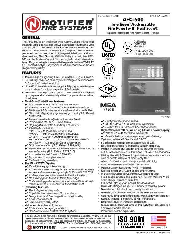
The Notifier FMM-1 is an intelligent addressable monitor module designed for use with Notifier's ONYX series and other compatible fire alarm control panels. This module allows conventional alarm initiating devices, such as manual pull stations, normally open contact devices, or waterflow switches, to be connected to an intelligent fire alarm system. It monitors the status of these devices and reports their condition (normal, alarm, or trouble) back to the control panel.
The FMM-1 module is a crucial component for integrating existing conventional devices into modern addressable fire detection systems, providing precise location identification for alarms and troubles.
Figur 1: Forside view of the Notifier FMM-1 module. This image displays the module's front face, featuring the "Notifier by Honeywell" branding and two small circular indicators, likely for status or activity.
2. Opsætning og installation
Installation of the FMM-1 module should only be performed by qualified personnel in accordance with all local and national electrical codes, and the manufacturer's instructions. Ensure that all power to the fire alarm control panel and associated circuits is disconnected before beginning installation.
2.1 Montering
The FMM-1 module is designed for mounting in a standard 4-inch square, 2-1/8 inch deep electrical box. It can also be mounted in a surface-mount box (SMB500) or a standard 1-gang box. The module includes mounting tabs for secure installation.

Figure 2: Front and back components of the Notifier FMM-1 module. This image illustrates both the front cover and the rear mounting plate, which houses the terminal connections for wiring.
2.2 Ledningsføring
The FMM-1 module connects to the Signaling Line Circuit (SLC) of the fire alarm control panel and to the conventional initiating device circuit (IDC). Refer to the specific wiring diagrams provided with the module and the fire alarm control panel for correct connections. Ensure proper polarity for all connections.
- SLC Connections: Connect the SLC input and output wires to the designated terminals on the module.
- IDC Connections: Connect the conventional initiating device circuit to the appropriate terminals. An End-of-Line Resistor (EOLR) must be installed at the last device on the IDC circuit as specified by the manufacturer to ensure proper supervision.
- Adressering: Set the unique address for the module using the rotary switches on the module. Each module on the SLC must have a distinct address.

Figur 3: Bagside view of the Notifier FMM-1 module with wiring details. This image provides a clear view of the terminal block for connecting to the fire alarm system's Signaling Line Circuit (SLC) and the initiating device circuit (IDC), along with product labels and certifications.
After wiring, verify all connections are secure and correct before applying power to the system.
3. Driftsprincipper
Once properly installed and addressed, the FMM-1 module operates by continuously monitoring the connected conventional initiating device circuit. It communicates the status of this circuit to the intelligent fire alarm control panel via the SLC.
- Normal tilstand: When the connected initiating device circuit is in a normal, non-alarm state, the module reports a normal status to the control panel.
- Alarmtilstand: Upon activation of a connected device (e.g., a pull station is activated, or a waterflow switch detects flow), the module detects the change in circuit status and immediately transmits an alarm signal to the control panel. The control panel will then initiate its programmed alarm sequence.
- Trouble State: If a fault occurs on the initiating device circuit (e.g., an open circuit, short circuit, or ground fault), the module detects this trouble condition and reports it to the control panel. The control panel will indicate a trouble condition, often with an audible signal and a display message indicating the module's address.
The module's LED indicators (if present) may provide local visual indication of its status, such as flashing during normal operation or solid during an alarm/trouble condition. Refer to the specific product documentation for LED behavior.
4. Vedligeholdelse
The Notifier FMM-1 module is designed for reliable, long-term operation with minimal maintenance. However, regular system-wide inspections and testing are crucial for ensuring the continued proper functioning of the fire alarm system.
- Visuel inspektion: Periodically inspect the module and its connections for any signs of physical damage, corrosion, or loose wiring.
- Systemtest: The fire alarm system, including all connected modules and devices, should be tested regularly by qualified personnel in accordance with NFPA 72 (National Fire Alarm and Signaling Code) and local authority having jurisdiction (AHJ) requirements. This includes testing the functionality of devices connected to the FMM-1 module to ensure they properly report to the control panel.
- Rensning: Rengør om nødvendigt forsigtigt modulets yderside med en blød, tør klud. Brug ikke slibende rengøringsmidler eller opløsningsmidler.
Any maintenance or repair work beyond simple visual inspection and cleaning should be performed by a certified fire alarm technician.
5. Fejlfinding
If the FMM-1 module or its connected devices are not functioning as expected, consider the following troubleshooting steps. Always ensure power is disconnected before inspecting wiring.
| Symptom | Mulig årsag | Løsning |
|---|---|---|
| Module reports trouble condition. | Open circuit, short circuit, or ground fault on IDC; incorrect EOLR; module addressing error. | Verify IDC wiring for breaks or shorts. Check EOLR value and placement. Confirm module address is unique and correctly set. |
| Module not communicating with control panel. | Incorrect SLC wiring; module address conflict; faulty module. | Check SLC wiring for proper polarity and continuity. Ensure no duplicate addresses on the SLC. If issues persist, module may need replacement. |
| Connected device does not report alarm. | Faulty initiating device; incorrect IDC wiring; module not configured correctly. | Test the initiating device directly. Verify IDC wiring to the device. Confirm module programming in the control panel. |
For complex issues or if troubleshooting steps do not resolve the problem, contact a certified fire alarm technician or Notifier technical support.
6. Specifikationer
The following are key specifications for the Notifier FMM-1 Intelligent Addressable Monitor Module:
- Modelnummer: FMM-1
- Mærke: Underretning
- Strømkilde: Corded Electric (via SLC)
- Varens vægt: Cirka 1.6 ounces (0.1 pund)
- Produktdimensioner: Cirka 4.9 x 4.9 x 1.3 tommer
- Alarmtype: Audible (via connected devices, reported to panel)
- UPC: 783863011221
- Fabrikant: Underretning
- Anvendelse: Indoor, dry applications only
- Certificeringer: UL Listed, FM Approved (for Fire Alarm and Security Equipment)

Figure 4: Notifier FMM-1 module as packaged. This image shows the module, its clear plastic packaging, and the included installation and maintenance instructions, along with minor accessories.
7. Garanti og support
For specific warranty information regarding the Notifier FMM-1 Intelligent Addressable Monitor Module, please refer to the warranty documentation provided with your purchase or contact your authorized Notifier distributor or reseller. Warranty terms typically cover defects in materials and workmanship for a specified period from the date of purchase.
For technical support, installation assistance, or service inquiries, please contact Notifier's official customer support channels or your certified fire alarm system installer. Always provide your product model number (FMM-1) and any relevant system details when seeking support.
Anmelderens embedsmand Webwebsted: www.notifier.com