1. Introduktion
This manual provides essential information for the safe and efficient installation, operation, and maintenance of the Generic ZUKED 310 Series Variable Frequency Drive (VFD) Inverter. This VFD is designed to control the speed and torque of AC induction motors by varying the motor input frequency and voltage. Please read this manual thoroughly before installation and operation to ensure proper use and to prevent damage or injury.
2. Sikkerhedsoplysninger
WARNING: Electrical shock hazard. Only qualified personnel should install, operate, and maintain this equipment.
- Always disconnect power before performing any wiring or maintenance. Wait at least 5 minutes after power-off for capacitors to discharge.
- Ensure proper grounding of the VFD and the motor.
- Do not touch internal components while power is applied or immediately after power-off.
- Protect the VFD from moisture, dust, corrosive gases, and direct sunlight.
- Bekræft input voltage matches the VFD's specifications before connecting power.

Figur 2.1: Front panel of the VFD, showing the display, control buttons, and a 'DANGER 5 min' warning indicating residual voltage after power-off.
3. Produktfunktioner
The ZUKED 310 Series VFD Inverter offers robust performance and versatile control for various industrial applications. Key features include:
- Wide Voltage Kompatibilitet: Supports 3-phase input/output for industrial motors, with models for 1-phase 220V input to 3-phase 220V output, and 3-phase 380V input to 3-phase 380V output.
- Precise Motor Control: Advanced vector control technology ensures precise torque and speed regulation with a typical speed accuracy of ±0.5%.
- Robust design: Compact structure with an IP55-rated dust and water-resistant enclosure, suitable for harsh workshop conditions.
- Integrated Automation: Features an integrated PID controller, RS485 communication interface, and multiple I/O ports for seamless automation system integration.
- Energieffektivitet: An energy-saving mode automatically adjusts output to match load demands, potentially reducing power consumption by 30%-60%.
- Beskyttelsesfunktioner: Includes comprehensive protection against overcurrent, overvoltage, overload, phase loss, and short circuits.
- Udgang Voltage forordning: Built-in Automatic Voltage Regulation (AVR) function maintains stable output voltage.

Figur 3.1: Overview of the ZUKED 310 Series VFD Inverter.

Figur 3.2: VFD model indicating 380V/220V compatibility and 11KW power rating.

Figur 3.3: VFD model indicating 220V/380V compatibility and various power ratings from 0.75KW to 5.5KW.
4. Specifikationer
| Specifikation | Værdi |
|---|---|
| Modelnummer | JBAQJAEEA-ZUKED-11KW-3PH380V-3PH380V |
| Input bindtage (1-phase) | AC 220V ±10 % |
| Udgang Voltage (3-phase from 1-phase input) | AC 0-240V |
| Input bindtage (3-phase) | AC 380V ±10 % |
| Udgang Voltage (3-phase from 3-phase input) | AC 0-440V |
| Udgangsstrømindstillinger | 0.75KW, 1.5KW, 2.2KW, 4KW, 5.5KW, 7.5KW, 11KW |
| Udgangsfrekvens | 0-320Hz |
| Kontrolmetode | V/F Control, Vector Control |
| Beskyttelsesfunktioner | Overstrøm, Overvoltage, Overload, Phase Loss, Short Circuit |
| Særlige funktioner | Simple PLC, Built-in PID, AVR Function |
| Pakkedimensioner | 0.39 x 0.39 x 0.39 cm (ca.) |
| Varens vægt | 3.53 ounces (Approximate) |
5. Installation & Wiring
5.1 Miljøkrav
- Temperatur: 0°C til 40°C (32°F til 104°F)
- Fugtighed: Mindre end 90 % RF, ikke-kondenserende
- Beliggenhed: Avoid direct sunlight, corrosive gases, flammable materials, and excessive dust. Ensure adequate ventilation.
5.2 Ledningsforbindelser
Proper wiring is crucial for safe and reliable operation. Refer to the wiring diagrams below for correct connections.

Figur 5.1: Single-phase and Three-phase wiring diagrams for the VFD.
5.2.1 Power Input (R, S, T / L1, L2)
- Single-Phase 220V Input: Connect the live wire to L1 and the neutral wire to L2.
- Three-Phase 380V Input: Connect the three phase wires to R, S, and T terminals.
- Always ensure a fuse is installed on the input line for protection.
5.2.2 Motor Output (U, V, W)
Connect the three motor phase wires to the U, V, and W terminals of the VFD. Ensure correct phase sequence for desired motor rotation. If the motor rotates in the wrong direction, swap any two of the U, V, W connections.
5.2.3 Braking Resistance (P+, PB)
If dynamic braking is required, connect an external braking resistor between the P+ and PB terminals. Refer to the VFD specifications for appropriate braking resistor values.
5.2.4 Grounding (PE)
Connect the PE (Protective Earth) terminal to a reliable ground point. Proper grounding is essential for safety and to minimize electromagnetic interference.
5.2.5 Kontrolterminaler
The VFD features various control terminals for external control signals, including digital inputs (DI), analog inputs (AI), analog outputs (AO), and communication ports (RS485). Refer to the detailed diagram for specific terminal functions.

Figur 5.2: Detaljeret view of the VFD's control and power terminals.

Figur 5.3: Side view of the VFD, showing model details and ventilation.
6. Opsætning og konfiguration
The VFD's control panel allows for parameter setting and monitoring. The display shows operational status and parameter values, while buttons like PRG, M-FUN, SHIFT, RUN, STOP/REST, UP, DOWN, and ENTER are used for navigation and input.
6.1 Grundlæggende parameterindstillinger
Upon initial power-up, it is essential to configure basic motor parameters and operating modes. Common parameters include:
- Motorens nominelle effekt: Set according to your motor's nameplate.
- Motor Nominel Voltage: Set according to your motor's nameplate.
- Motor nominel strøm: Set according to your motor's nameplate.
- Maximum Output Frequency: Typically 50Hz or 60Hz, but can be set up to 320Hz.
- Acceleration/Deceleration Time: Adjust these parameters to control how quickly the motor speeds up or slows down.
- Kontroltilstand: Select between V/F control (Volts per Hertz) or Vector control based on application requirements. Vector control offers better performance for demanding applications.
Refer to the detailed parameter list in the full product manual (if available) for advanced settings, including PID control, simple PLC functions, and communication settings.
7. Betjening
Once the VFD is correctly installed and configured, operation is straightforward.
7.1 Starting the Motor
Tryk på LØBE button on the control panel or activate the corresponding external run command (if configured). The motor will accelerate to the set frequency according to the acceleration time parameter.
7.2 Stopping the Motor
Tryk på STOP/REST button on the control panel or activate the corresponding external stop command. The motor will decelerate to a stop according to the deceleration time parameter.
7.3 Adjusting Frequency/Speed
Brug ▲ (Op) og ▼ (Down) arrow buttons on the control panel to adjust the output frequency, thereby changing the motor speed. The display will show the current output frequency or motor speed.
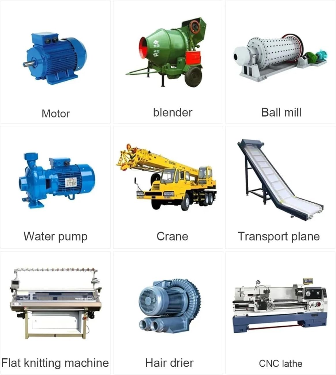
Figur 7.1: Examples of industrial applications suitable for the VFD.
8. Vedligeholdelse
Regular maintenance helps ensure the longevity and reliable operation of your VFD.
- Rensning: Periodically clean the VFD's exterior and cooling fins to prevent dust accumulation, which can hinder heat dissipation. Use a soft, dry cloth. Do not use liquid cleaners.
- Inspektion: Regularly inspect wiring connections for tightness and signs of corrosion or damage. Check for any unusual noises or odors during operation.
- Miljøtjek: Sørg for, at driftsmiljøet holder sig inden for de angivne temperatur- og fugtighedsgrænser.
- Ventilatortjek: Verify that the cooling fan (if present) is operating correctly and not obstructed.
WARNING: Always disconnect power and wait for the discharge period before performing any maintenance or inspection.
9. Fejlfinding
Dette afsnit indeholder vejledning til almindelige problemer. Kontakt teknisk support ved komplekse problemer.
| Symptom/Error Code | Mulig årsag | Løsning |
|---|---|---|
| Motoren kører ikke | No power, incorrect wiring, stop command active, parameter error. | Check power supply, verify wiring, ensure run command is active, check motor parameters. |
| Overstrømsfejl | Motor overload, short circuit in motor/cables, acceleration time too short. | Reduce load, check motor and cables, increase acceleration time, verify motor parameters. |
| Overvoltage fejl | Deceleration time too short, input voltage too high, regenerative load. | Increase deceleration time, check input voltage, consider adding a braking resistor. |
| Undervoltage fejl | Input voltage too low, power supply instability. | Kontroller input voltage, ensure stable power supply. |
| Overbelastningsfejl | Motor or VFD overloaded. | Reduce mechanical load, check motor parameters, ensure VFD is correctly sized for the motor. |
10. Garanti og support
Specific warranty terms and conditions for the Generic ZUKED 310 Series VFD Inverter are not provided within the product details. Please refer to your purchase documentation or contact your vendor for warranty information and technical support.


