1. Introduktion
The Generic LCR-P1 Transistor Tester is a versatile electronic component testing device designed for efficient identification and measurement of various components. It features intelligent identification, anti-burn protection, and a replaceable patch holder, making it suitable for a wide range of testing needs, including transistors, diodes, capacitors, resistors, inductors, and battery voltage.
2. Pakkens indhold
Kontroller venligst, at alle nedenstående varer er inkluderet i din pakke:
- 1x LCR-P1 Transistor Tester
- 1x Patch Test Board
- 1x Data Cable (Type-C)
- 1x Description (Manual)
- 3x Test Hooks

Image 2.1: The LCR-P1 Transistor Tester along with its included accessories: a Type-C data cable, a patch test board, and three test hooks.
3. Produktfunktioner
- Efficient Component Identification: Automatically identifies device parameters with a single button press upon insertion.
- Anti-Burn Protection: Features a mechanism to discharge undischarged capacitors upon insertion, protecting the meter.
- Replaceable Patch Holder: Innovative design allows for easy adaptation to various testing requirements.
- Infrared Signal Decoding: Supports decoding of infrared signals, useful for remote control testing.
- Precise Zener Diode Testing: Dedicated measurement channel for Zener diodes, with a measurable range of 0.01-32V.
- Kompakt og bærbart design: Small and lightweight for easy transport and use anywhere.
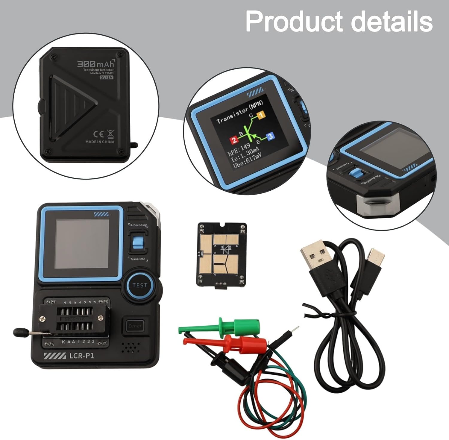
Billede 3.1: Detaljeret view of the LCR-P1 tester, showing its screen, patch holder, and the Type-C charging port. The back of the device indicates a 300mAh battery.

Image 3.2: The LCR-P1 Transistor Tester displayed with its patch test board, test hooks, and Type-C data cable, highlighting the complete set of components.
4. Opsætning
- Udpakning og inspektion: Carefully remove all components from the packaging. Inspect the tester and accessories for any visible damage.
- Indledende opladning: Before first use, ensure the device is fully charged. Connect the provided Type-C data cable to the tester's charging port and a 5V/1A power source. The battery capacity is 300mAh.
- Connecting Test Accessories:
- Patch Test Board: For surface-mount components or specific test configurations, insert the patch test board into the designated socket on the tester.
- Test Hooks: For through-hole components or connecting to larger circuits, attach the test hooks to the appropriate terminals on the tester or patch test board.
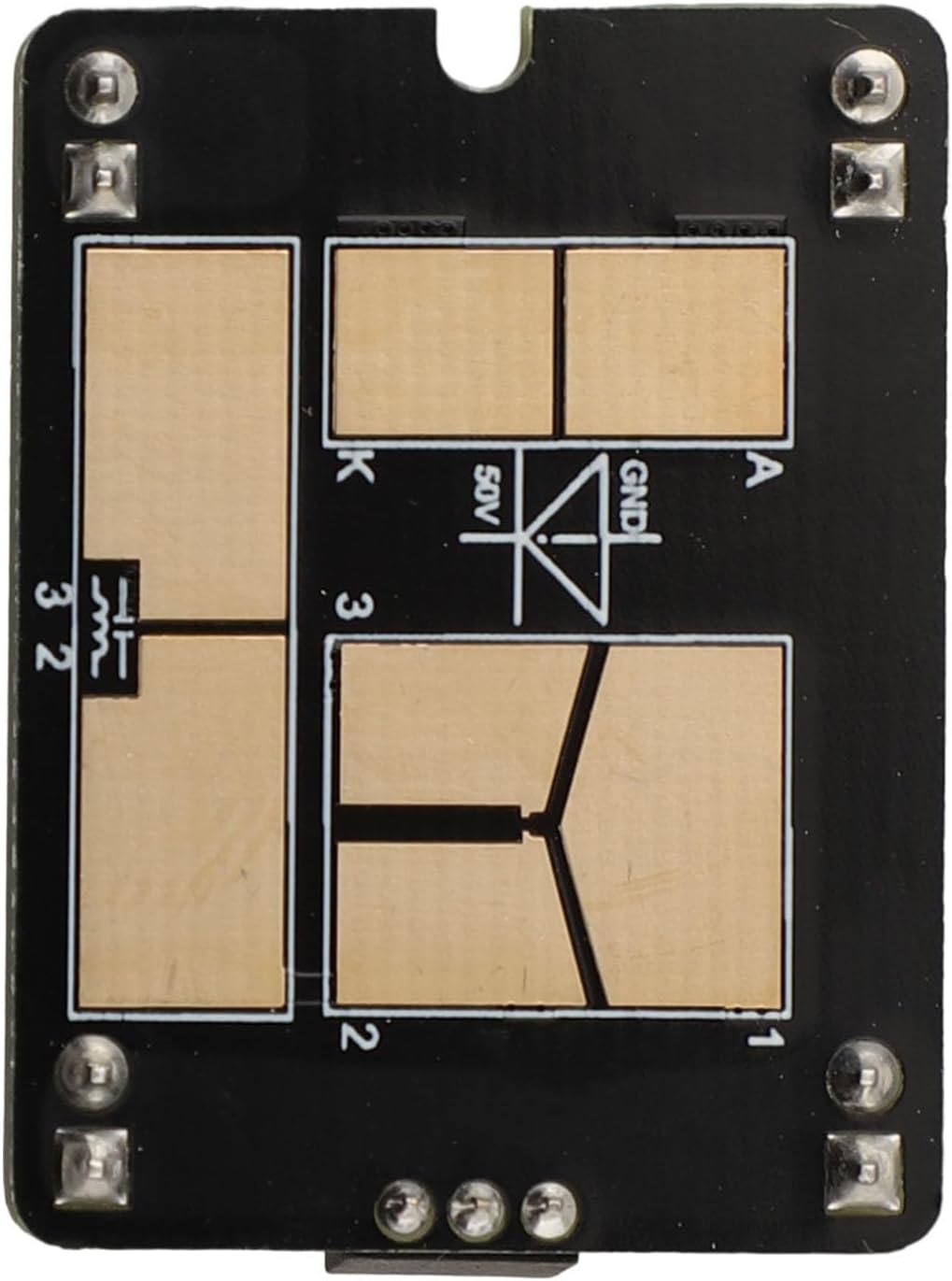
Billede 4.1: Et nærbillede view of the replaceable patch test board, showing its contact pads and markings for component placement.
5. Betjeningsvejledning
The LCR-P1 Transistor Tester is designed for straightforward operation. Always ensure the component to be tested is discharged, especially capacitors, to prevent damage to the tester.
- Tænd/sluk: Press the 'TEST' button to power on the device. The device will automatically power off after a period of inactivity to conserve battery.
- Component Testing (General):
- Insert the component leads into the ZIF (Zero Insertion Force) socket or connect via test hooks/patch board.
- Forsigtigt clamp komponenten.
- Press the 'TEST' button. The tester will automatically identify the component type (e.g., transistor, diode, resistor, capacitor, inductor) and display its parameters on the 1.44-inch screen.

Image 5.1: A close-up of the LCR-P1 tester's screen displaying the results of a transistor test, including NPN type, hFE, collector current (Ic), and base-emitter voltage (Ube).
- Zener Diode Testing: For Zener diodes, ensure the device is powered on. The tester has a dedicated channel for Zener diodes, allowing measurement within the 0.01-32V range. Connect the Zener diode to the appropriate terminals and press 'TEST'.
- Infrared (IR) Decoding: The tester supports infrared signal decoding. Point an IR remote control towards the IR receiver on the tester and press a button on the remote. The tester will display the decoded protocol and code.
- Batteri Voltage Test: Connect the battery to the designated terminals. The tester can measure battery voltage fra 0.1-4.5V.

Billede 5.2: En vinklet view of the LCR-P1 Transistor Tester, highlighting its compact form factor and the layout of its controls and display.
6. Vedligeholdelse
- Rensning: Brug en blød, tør klud til at rengøre enheden. Brug ikke slibende rengøringsmidler eller opløsningsmidler.
- Opbevaring: Opbevar testeren et køligt, tørt sted væk fra direkte sollys og ekstreme temperaturer.
- Batteripleje: Recharge the internal lithium battery regularly, especially if the device will not be used for an extended period, to maintain battery health.
7. Fejlfinding
- Enheden tænder ikke: Ensure the battery is charged. Connect the Type-C cable to a 5V/1A power source and allow it to charge for at least 30 minutes before attempting to power on again.
- Incorrect readings or no detection:
- Verify that the component leads are properly inserted and making good contact in the ZIF socket or with the test hooks.
- Ensure the component is not damaged.
- For capacitors, ensure they are fully discharged before testing.
- Skærmen er blank eller flimrer: Genoplad batteriet. Hvis problemet fortsætter, skal du kontakte kundesupport.
8. Specifikationer
| Parameter | Værdi |
|---|---|
| Model | LCR-P1 |
| Vise | 1.44 tommer |
| Batterikapacitet | 300mAh lithium batteri |
| Opladningsspecifikation | Type-C, 5V/1A |
| Dimensioner | 71 × 87 × 28mm (2.8 x 3.4 x 1.1 inches) |
| Vægt | 140 gram (4.9 ounce) |
| Transistors (Triodes) | 10 |
| dioder | Positive pressure drop < 4.5V |
| Stabilization Diode (Zener) | 0.01-4.5V, 0.01-32V |
| Field Effect Tube | JFET, IGBT, MOSFET |
| Unidirectional/Dual-directional Sailor | Åben bindtage < 5V, Mental Touch Dive current < 6mA |
| Kondensator | 25pF ~ 100mF |
| Modstand | 0.01Ω - 50MΩ |
| Induktans | 10µH - 1000µH |
| Batteritest | 0.1-4.5V |
| Infrared Remote Control Decoding | Protocol infrared code |
9. Garanti og support
For garantioplysninger eller teknisk support henvises til den dokumentation, der fulgte med dit køb, eller kontakt sælgeren direkte. Gem din købskvittering som købsbevis.
10. Ansøgning Eksamples

Image 10.1: A technician using the LCR-P1 Transistor Tester during the inspection and repair of an air conditioning unit, demonstrating its utility in field service.

Image 10.2: The LCR-P1 Transistor Tester being used by a technician while performing maintenance on a boiler system, indicating its applicability in industrial and home appliance repair.

Image 10.3: A collage illustrating the LCR-P1 Transistor Tester's use in diverse scenarios, including electronic circuit development, appliance repair, and educational settings.


