
1. Introduktion
The Sparkleiot ESP32-C3 Mini is a high-performance, energy-efficient IoT development board based on the Espressif ESP32-C3 dual-mode WLAN chip. This 32-bit RISC-V CPU includes an FPU for single-precision floating-point arithmetic, offering robust processing capabilities. It supports IEEE 802.11 b/g/n WLAN and Bluetooth 5.0 protocols, providing excellent RF performance. The board is compact, ideal for portable devices and small projects, and features a single-sided surface mount design.
Nøglefunktioner omfatter:
- Powerful 32-bit RISC-V CPU up to 160 MHz.
- Integrated Wi-Fi (802.11 b/g/n) and Bluetooth 5.0.
- Ultra-low power consumption in Deep Sleep mode (approx. 43µA).
- Rich interfaces: 1x I2C, 1x SPI, 2x UART, 11x GPIO (PWM), 4x ADC.
- External IPEX antenna support for enhanced signal strength.
- Integrated 4MB Flash memory.
2. Opsætning
2.1 Board Overview
The ESP32-C3 Mini development board is designed for ease of use in various IoT applications. It features a USB-C port for power and data, along with pin headers for GPIO access.

Figur 1: Top og bund view of the ESP32-C3 Mini Development Board.

Figure 2: ESP32-C3 Mini Development Board with pin headers.
2.2 Strømforsyning
The board can be powered via the USB-C port or an external power supply. If using an external power supply, connect the positive lead to the 5V pin and the negative lead to the GND pin. The board supports an external power supply range of 3.3V to 6V. When an external power supply is connected, the USB port should not be used for power simultaneously. Ensure correct polarity to prevent damage to the board or power source.
2.3 Antenneforbindelse
The board includes an IPEX antenna connector for attaching an external 2.4 GHz antenna. This is recommended for applications requiring stronger or more stable wireless signals. The board also has an onboard antenna.

Figure 3: Connecting an external 2.4G IPEX antenna.
By default, the onboard antenna is used. To use an external antenna, a modification to the resistor position on the board is required. Refer to the manufacturer's documentation or community resources for detailed instructions on this modification.
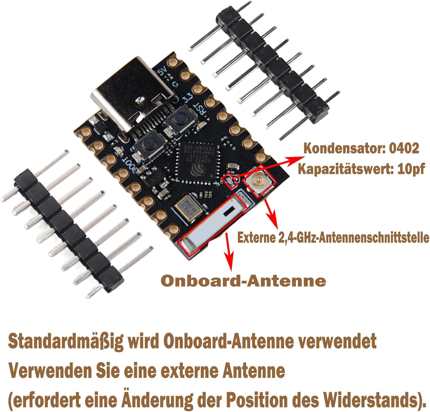
Figure 4: Onboard vs. External Antenna Interface.
2.4 Pinout-diagram
Understanding the pinout is crucial for connecting peripherals and programming the board.

Figure 5: ESP32-C3 Mini Development Board Pinout and Dimensions.
The board provides 11 digital I/O pins (which can also function as PWM pins) and 4 analog I/O pins (which can function as ADC pins). It supports serial communication protocols including UART, I2C, and SPI.
3. Betjeningsvejledning
3.1 Programmering af bestyrelsen
The ESP32-C3 Mini can be programmed using various development environments, such as the Espressif IDF (IoT Development Framework) or Arduino IDE with the ESP32 core. Connect the board to your computer via the USB-C port. The board features a reset button and a bootloader mode button for programming and debugging.
- Nulstil knap: Press to restart the board.
- Bootloader Button: Hold down the Boot button, then press and release the Reset button, then release the Boot button to enter bootloader mode for flashing new firmware.
3.2 Wi-Fi- og Bluetooth-forbindelse
The ESP32-C3 supports 2.4 GHz Wi-Fi (802.11b/g/n) and Bluetooth 5.0. It can operate in Station mode, SoftAP mode, SoftAP+Station mode, or mixed mode for Wi-Fi. Refer to the Espressif documentation and examples for detailed programming instructions on establishing wireless connections.
3.3 Brug af periferiudstyr
Utilize the available interfaces (I2C, SPI, UART, GPIO, ADC) to connect sensors, actuators, and other modules. Consult the pinout diagram (Figure 5) for correct pin assignments. Ensure proper voltage levels when connecting external components to avoid damage.
4. Vedligeholdelse
To ensure the longevity and proper functioning of your ESP32-C3 Mini Development Board, follow these maintenance guidelines:
- Håndteres med forsigtighed: Undgå at tabe boardet eller udsætte det for fysiske stød.
- Statisk udladning: Always handle the board in an ESD-safe environment to prevent damage from static electricity.
- Strømforsyning: Use only power supplies within the specified voltage range (3.3V to 6V). Never short-circuit the positive and negative terminals, especially during soldering, as this can damage the board or power source.
- Renhed: Hold printpladen fri for støv, snavs og fugt. Brug en blød, tør børste eller trykluft, hvis rengøring er nødvendig. Undgå at bruge væsker.
- Opbevaring: Opbevar pladen et tørt, køligt sted, væk fra direkte sollys og ekstreme temperaturer.
5. Fejlfinding
If you encounter issues with your ESP32-C3 Mini Development Board, consider the following troubleshooting steps:
- Ingen strøm: Verify that the USB-C cable is securely connected and functional, or that the external power supply is providing the correct voltage (3.3V-6V) and is properly connected to the 5V and GND pins.
- Programmeringsfejl: Ensure the correct board and port are selected in your IDE. Try entering bootloader mode manually (hold Boot, press/release Reset, then release Boot) before attempting to flash firmware. Check your code for syntax errors.
- Problemer med Wi-Fi/Bluetooth-forbindelse: Confirm that your antenna is properly connected (if using an external one) and that the resistor modification for external antenna use has been performed if necessary. Check your code for correct Wi-Fi/Bluetooth initialization and credentials.
- Perifer funktionsfejl: Double-check all wiring connections to your peripherals. Ensure that the correct pins are being used according to the pinout diagram and that the peripheral is receiving adequate power.
- Computeren genkender ikke kortet: Try a different USB-C cable or USB port. Ensure that the necessary USB drivers are installed on your computer.
6. Specifikationer
| Feature | Beskrivelse |
|---|---|
| CPU | ESP32-C3, 32-bit RISC-V single-core processor, up to 160 MHz |
| Wi-Fi | 802.11b/g/n, 2.4 GHz, Station/SoftAP/SoftAP+Station/Mixed modes |
| Bluetooth | Bluetooth 5.0 |
| Hukommelse | 400KB SRAM, 384KB ROM, 4MB integrated Flash |
| Strømforbrug | Deep Sleep current consumption approx. 43µA |
| Grænseflader | 1x I2C, 1x SPI, 2x UART, 11x GPIO (PWM), 4x ADC |
| Antenne | Onboard antenna, 2.4G IPEX external antenna connector |
| Sikkerhedsfunktioner | Hardware cryptographic accelerators (AES-128/256, Hash, RSA, HMAC, Digital Signature, Secure Boot) |
| Dimensioner | 22.52 x 18 mm |
| Operation Voltage | 3.3V - 6V (external power supply) |
| Integreret LED | Blue LED on GPIO8 |
7. Garanti og support
Information regarding product warranty and technical support is not available in the provided product data. For details on warranty coverage, return policies, or technical assistance, please refer to the Sparkleiot official webwebstedet eller kontakt dit købssted.