
1. Introduktion
This manual provides detailed instructions for the safe and effective operation of your WLLKIY ET31C/ET32C Automotive Signal Generator Multimeter. This device combines the functions of a signal generator and a multimeter, designed for automotive diagnostics and testing. It can simulate various automotive sensor signals, test ignition coils, and perform standard multimeter measurements.

Figure 1: WLLKIY ET31C/ET32C Automotive Signal Generator Multimeter and included accessories.
2. Sikkerhedsoplysninger
Læs og forstå alle sikkerhedsadvarsler og betjeningsvejledninger, før du bruger dette instrument. Manglende overholdelse af disse instruktioner kan resultere i elektrisk stød, brand eller alvorlig personskade.
- Brug altid passende personlige værnemidler, såsom sikkerhedsbriller, når du arbejder på køretøjer.
- Brug ikke enheden, hvis den ser beskadiget ud, eller hvis testledningerne er i stykker.
- Ensure the device is powered off before connecting or disconnecting test leads.
- Undgå kontakt med strømførende kredsløb.
- Do not exceed the maximum input ratings specified in the specifications section.
- Hold enheden væk fra fugt og ekstreme temperaturer.
3. Pakkens indhold
Bekræft, at alle nedenstående varer er til stede i din pakke:
- 1 x Signal Generator Multimeter (ET31C or ET32C model)
- 1 x par prøveledninger
- 1 x Pair of Alligator Clip Wires
- 1 x USB Type-C Cable (for ET32C charging, or data for both)
- 1 x engelsk brugervejledning
Note: For ET31C, 3x 1.5V AAA batteries are required and are not included. The ET32C model includes a built-in 4.2V lithium battery.
4. Opsætning
4.1 Tænding af enheden
- For ET31C: Open the battery compartment on the back of the device. Insert 3x 1.5V AAA batteries, ensuring correct polarity. Close the compartment.
- For ET32C: The device has a built-in rechargeable battery. If the battery is low, connect the included USB Type-C cable to the device and a suitable USB power source (e.g., computer USB port, USB wall adapter).
- Press and hold the power button (usually marked with a power symbol) to turn on the device.
4.2 Tilslutning af testledninger
Connect the test leads or alligator clip wires to the appropriate input jacks on the bottom of the device.
- COM Jack: Common (negative) input for all measurements and signal output.
- VΩHz-stik: Positiv indgang for volumentage. modstands-, frekvens-, kapacitans-, diode- og kontinuitetsmålinger.
- Udgangsstik: Positive output for signal generation.
5. Betjeningsvejledning
5.1 Skift mellem tilstande
The device operates in two primary modes: Signal Generator and Multimeter. Use the MODE button to switch between these functions. The current mode will be displayed on the 2.8-inch screen.
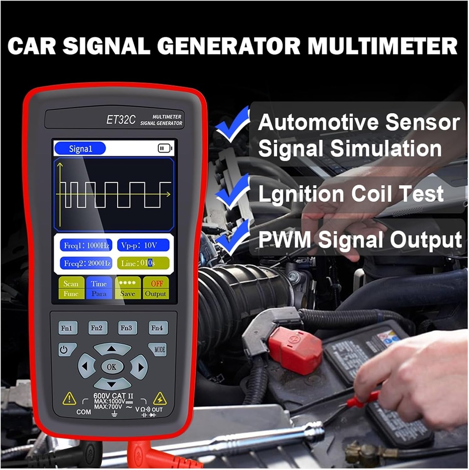
Figure 2: The device in use for automotive sensor signal simulation and ignition coil testing.
5.2 Signalgeneratorfunktioner
This mode allows you to generate various electrical signals for testing automotive components.
- Signaltyper: Sine wave, Square wave, Combined wave (e.g., 58+2, 10+1 missing teeth), Scan wave, and DC wave.
- Frekvensområde: 1Hz to 9999Hz (adjustable in 1Hz steps).
- Udgang Voltage (Peak-to-Peak): -12V to +12V (adjustable in 1V steps).
- Duty Cycle (for Square Wave): 1 % til 99 %.
- Scan Wave: Simulates crankshaft/camshaft signal changes from low to high speed (scan time 1s to 999s).
- Combined Wave: Allows setting of missing teeth signals (e.g., 58+2, 10+1). Maximum combined wave combinations: 99+99.
- Bølgeformlagring: The instrument supports storing up to 50 sets of waveform parameters.

Figure 3: Display illustrating combined wave signal generation with missing teeth settings.

Figure 4: The device's waveform storage feature, allowing up to 50 sets of parameters to be saved.
5.2.1 Automotive Signal Simulation
The signal generator can simulate Hall-type and magneto-electric crankshaft and camshaft signals. This is useful for diagnosing engine management systems without needing to run the engine.
- Supports simulation for both gasoline and diesel vehicles.
- Simulate various sensor outputs to test ECU responses.

Figure 5: The device functioning as a vehicle maintenance signal source, simulating sensor outputs.
5.2.2 Ignition Coil Control
The device can control ignition coils, solenoid valves, and relays to test their functionality.
- Coil control power: Less than 30V/1A.
- Connect the output to the component to be tested and observe its operation.

Figure 6: Screen showing the ignition coil test function, used to verify normal operation of coils, solenoid valves, and relays.
5.3 Multimeterfunktioner
In multimeter mode, the device performs standard electrical measurements.
- DC bindtage: Max 1000V.
- AC Voltage: Max 750V.
- Modstand: Max 40MΩ.
- Kapacitans: Max 100uF.
- Frekvens: Max 50KHz.
- Driftscyklus: 0.1 % til 99.9 %.
- Diode test: 0V til 1.5V.
- Kontinuitetstest: Resistance value for continuity detection: Max 30Ω.
- Vise: 4000 counts, updates 3 times per second.

Figure 7: The device's multimeter display showing a measurement, alongside details of the 2.8-inch screen with 320x480 resolution.
6. Specifikationer
6.1 Generelle specifikationer
- Vise: 2.8-inch, 320 * 480 resolution
- Touchskærm: Ikke understøttet
- USB-grænseflade: Type-C USB
- Battery (ET31C): 3 * 1.5V AAA batteries (not included)
- Battery (ET32C): Indbygget 4.2V lithiumbatteri
- Opbevaringstemperatur: -20°C til 60°C (-4°F til 140°F)
- Driftstemperatur: 0°C til 50°C (32°F til 122°F)
- Fugtighed: <85% relativ luftfugtighed (ikke-kondenserende)
- Produktmål (LxBxH): 134 mm * 69 mm * 25 mm
- Produktvægt: 125 g (excluding accessories)
6.2 Parametre for signalgenerator
- Sine Wave/Square Wave Frequency Range: 1Hz ~ 9999Hz
- Sine Wave/Square Wave Frequency Step: 1 Hz
- Sine Wave/Square Wave Peak Range: -12V ~ +12V
- Sine Wave/Square Wave Peak Step: 1V
- Scan Wave Scan Time Range: 1s ~ 999s
- Maximum Combined Wave Combinations: 99+99
- Udgang Voltage Område: -12V ~ +12V
- Udgang Voltage Trin: 1V
- Coil Control Power: Less than 30V/1A
- Bølgeformlagring: 50 sæt
- Duty Setting (for Square Wave only): 1 % ~ 99 %
6.3 Multimeterparametre
- Maksimal DC-indgang Voltage: 1000V
- Maksimal AC-indgang Voltage: 750V
- Maximum Measured Resistance: 40MΩ
- Maximum Measured Capacitance: 100uF
- Maximum Frequency Measurement: 50 KHz
- Duty Cycle Measurement Range: 0.1 % ~ 99.9 %
- Diode Measurement Range: 0V ~ 1.5V
- Maximum Resistance for Continuity Detection: 30Ω
- Visningstællinger: 4000 tæller
- Opdateringshastighed: 3 gange i sekundet
7. Vedligeholdelse
- Rensning: Tør enheden af med en blød, damp klæde. Brug ikke slibende rengøringsmidler eller opløsningsmidler.
- Opbevaring: Store the device in a cool, dry place away from direct sunlight and extreme temperatures. If storing for extended periods, remove AAA batteries from the ET31C model.
- Battery Care (ET32C): For optimal battery life, avoid fully discharging the battery frequently. Charge the device regularly if not in use for long periods.
- Prøveemner: Undersøg testledningerne for eventuelle skader (snit, revner) før hver brug. Udskift beskadigede ledninger med det samme.
8. Fejlfinding
| Problem | Mulig årsag | Løsning |
|---|---|---|
| Enheden tænder ikke. |
|
|
| Incorrect readings in Multimeter mode. |
|
|
| No signal output from Signal Generator. |
|
|
9. Garanti og support
For warranty information and technical support, please refer to the documentation provided with your purchase or contact WLLKIY customer service directly. Contact details can typically be found on the manufacturer's official webwebstedet eller på produktemballagen.