Supermicro MBD-X10DRG-O+-CPU
Supermicro X10DRG-O+-CPU Motherboard User Manual
Model: MBD-X10DRG-O+-CPU
1. Introduktion
This user manual provides comprehensive instructions for the installation, configuration, and maintenance of the Supermicro X10DRG-O+-CPU Motherboard. This motherboard is designed for high-performance computing environments, supporting dual Intel Xeon E5-2600 v3/v4 processors and extensive memory configurations.
Please read this manual thoroughly before beginning the installation process to ensure proper setup and operation.
2. Sikkerhedsoplysninger
Overhold altid følgende sikkerhedsforanstaltninger, når du håndterer bundkortet og andre computerkomponenter:
- Sørg for, at strømforsyningen er afbrudt fra stikkontakten, før du installerer eller fjerner komponenter.
- Bær en antistatisk håndledsrem, eller rør ofte ved en jordforbundet metalgenstand for at aflade statisk elektricitet.
- Hold bundkortet i kanterne for at undgå at berøre følsomme komponenter.
- Hold bundkortet væk fra væsker og ekstreme temperaturer.
- Refer to the safety guidelines provided with other components (CPU, RAM, etc.) for additional precautions.
3. Pakkens indhold
Verify that all items are present in the package. If any item is missing or damaged, contact your vendor immediately.
- Supermicro X10DRG-O+-CPU Motherboard
- I / O-skjold
- SATA-kabler (antallet kan variere)
- Hurtig referencevejledning
- Driver-cd/dvd (eller link til download af drivere)
4. Bundkortlayout
Nedenfor er en overview of the Supermicro X10DRG-O+-CPU Motherboard, highlighting key components and connectors.
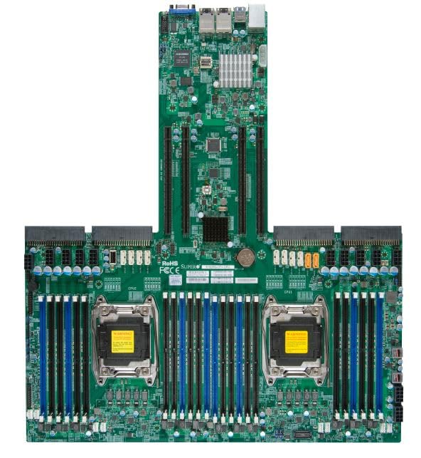
Figure 4.1: Supermicro X10DRG-O+-CPU Motherboard. This image displays the full motherboard, showing the dual CPU sockets, numerous DDR4 DIMM slots, PCIe expansion slots, and various I/O ports and connectors.
Nøglekomponenter:
- CPU Sockets (LGA 2011-3): Two sockets for Intel Xeon E5-2600 v3/v4 processors.
- DDR4 DIMM Slots: Multiple slots supporting up to 3072 GB of ECC DDR4 memory.
- PCIe-udvidelsesslots: Various PCIe 3.0 slots for graphics cards, network cards, and other expansion devices.
- SATA porte: Connectors for SATA 3.0 storage devices.
- USB-porte: USB 2.0 and USB 3.0 headers and rear panel ports.
- LAN-porte: Ethernet ports for network connectivity.
- Strømstik: ATX 24-pin, 8-pin EPS, and 4-pin power connectors.
5. Opsætning
Follow these steps for proper installation of the motherboard and its components.
5.1 CPU installation
- Open the CPU socket retention levers.
- Juster omhyggeligt CPU'en med soklen, og sørg for, at det trekantede mærke på CPU'en matcher mærket på soklen.
- Placer forsigtigt CPU'en i soklen uden at tvinge den.
- Luk fastholdelseshåndtagene for at fastgøre CPU'en.
- Apply thermal paste and install the CPU cooler according to the cooler manufacturer's instructions.
5.2 Installation af hukommelse (RAM)
- Åbn klipsene i begge ender af DIMM-stikket.
- Juster hakket på DDR4-hukommelsesmodulet med nøglen i DIMM-stikket.
- Sæt modulet godt ind i stikket, indtil klipsene klikker på plads.
- Repeat for all desired memory modules, following the motherboard's memory population guidelines for optimal performance.
5.3 Installation af lagerenhed
- Tilslut den ene ende af SATA-datakablet til en SATA-port på bundkortet.
- Tilslut den anden ende af SATA-datakablet til din SATA-harddisk eller SSD.
- Tilslut et SATA-strømkabel fra din strømforsyning til lagerenheden.
5.4 Installation af udvidelseskort
- Select an appropriate PCIe slot for your expansion card (e.g., GPU, network card).
- Fjern det tilsvarende dæksel til sloten fra dit pc-kabinet.
- Juster udvidelseskortet med stikket, og tryk godt ned, indtil det sidder helt på plads.
- Secure the card with a screw or retention clip to the PC case.
5.5 Strømforbindelser
- Tilslut 24-bens ATX-strømstikket fra din strømforsyning til hovedstrømforsyningen på bundkortet.
- Connect the 8-pin EPS (CPU) power connector(s) to the corresponding headers near the CPU sockets.
- Sørg for, at alle strømkabler er korrekt tilsluttet.
5.6 Frontpanelforbindelser
Connect the front panel cables (Power LED, HDD LED, Power Switch, Reset Switch, USB, Audio) from your PC case to the corresponding headers on the motherboard. Refer to the motherboard's silkscreen labels for correct pin assignments.
6. Betjening
6.1 BIOS/UEFI-opsætning
Upon first boot, you may need to enter the BIOS/UEFI setup utility to configure system settings. Typically, you can access this by pressing DEL or F2 during the POST (Power-On Self-Test) sequence. Common settings to configure include boot order, date/time, and enabling/disabling specific features.
6.2 Driverinstallation
After installing your operating system, install the necessary drivers for the motherboard's chipsets, LAN, audio, and other integrated components. Drivers can be found on the included driver CD/DVD or downloaded from the Supermicro official webwebsted.
6.3 Installation af operativsystem
Insert your operating system installation media (USB drive or DVD) and follow the on-screen prompts to install the OS. Ensure the boot order in BIOS/UEFI is set to prioritize your installation media.
7. Vedligeholdelse
7.1 Rengøring
Fjern regelmæssigt støv fra bundkortet og komponenterne med trykluft. Sørg for, at systemet er slukket og frakoblet stikket, før rengøring. Undgå at bruge væsker eller slibende materialer.
7.2 firmwareopdateringer
Kontroller Supermicro regelmæssigt website for updated BIOS/UEFI firmware. Firmware updates can improve stability, performance, and add support for new hardware. Follow the provided instructions carefully when performing a firmware update to avoid system damage.
8. Fejlfinding
Dette afsnit indeholder løsninger på almindelige problemer, du kan støde på.
| Problem | Mulig årsag | Løsning |
|---|---|---|
| Systemet tænder ikke. | Løse strømkabler, defekt strømforsyning, forkerte tilslutninger på frontpanelet. | Check all power connections (24-pin, 8-pin EPS). Verify front panel power switch connection. Test power supply. |
| Ingen skærmudgang. | Incorrectly seated GPU, faulty monitor cable, no integrated graphics. | Reseat the graphics card. Check monitor cable connections. Ensure monitor is on correct input. |
| System beeps repeatedly. | Memory (RAM) issue. | Reseat RAM modules. Try one module at a time. Refer to BIOS beep codes for specific diagnosis. |
| Operativsystemet blev ikke fundet. | Incorrect boot order, loose SATA cable, unformatted drive. | Check BIOS/UEFI boot order. Reseat SATA cables. Ensure drive is properly formatted and OS installed. |
9. Specifikationer
Detailed technical specifications for the Supermicro X10DRG-O+-CPU Motherboard.
- Modelnummer: MBD-X10DRG-O+-CPU
- Mærke: Supermicro
- CPU support: Dual Intel Xeon E5-2600 v3/v4 Processors (LGA 2011-3)
- Maksimal RAM-hukommelsesstørrelse: 3072 GB DDR4 ECC
- Understøttet systembusstandard: SATA 3
- S/PDIF-stiktype: Optisk
- Pakkedimensioner: 25 x 25 x 4 tommer
- UPC: 672042176427
- Dato først tilgængelig: 21. juni 2023
10. Garanti og support
For garantioplysninger og teknisk support henvises til den officielle Supermicro-brochure. webwebstedet eller kontakt dit købssted. Gem din købsbevis til garantikrav.
Supermicro Officiel Webwebsted: www.supermicro.com
Ask a question about this manual
Ask about setup, troubleshooting, compatibility, parts, safety, or missing instructions. Manuals+ will review the question and use this page’s manual context to help answer it.