
1. Introduktion
The EC Buying ZK-PP1K is a versatile PWM and pulse signal generator designed for various electronic applications. This device offers two primary modes: PWM mode for continuous frequency and duty cycle control, and Pulse mode for adjustable positive/negative pulse width, delay, and pulse count. It features a wide voltage input range and anti-reverse connection protection, making it suitable for controlling DC motors, stepper motors, servo motors, and replacing PLC pulse signals.
2. Produktfunktioner
- Dual Mode Operation: Switch between PWM mode (continuous frequency and duty cycle) and PULSE mode (adjustable positive/negative pulse width, delay, and pulse count).
- Start/Stop Functionality: Includes a dedicated button for controlling signal output (ON/OFF). The ZK-PP1K also supports external switch control.
- Wide Voltage Indgang: Operates within a 3.3V to 30V range, featuring built-in anti-reverse polarity protection.
- Klar LED-skærm: Provides real-time display of frequency, duty cycle, pulse count, and other parameters.
3. Produktspecifikationer

This image displays the ZK-PP1K PWM Pulse Signal Generator alongside its key specifications, including working voltage, frequency range, duty cycle range, number of pulses, delay output time, positive and negative pulse width length, and signal carrying capacity.
| Specifikation | Værdi |
|---|---|
| Working Voltage | 3.3V ~ 30V (with anti-reverse polarity protection) |
| Frekvensområde | 1Hz ~ 150KHz (accuracy approx. 1%) |
| Duty Cycle Range | 0-100% (1% step) |
| Antal impulser | 1-9999, or infinite (displayed as '----') |
| Delay Output Time | 0.000s - 9999s (minimum 1ms) |
| Positive/Negative Pulse Width Length | 0.000s - 9999s (minimum 1ms) |
| Signal Carrying Capacity | Less than 30mA (for ZK-PP1K) |
| Display Type | LED |
| Materiale | Plast |
| Dimensioner | Cirka 7.09 cm x 3.99 cm (2.79 tommer x 1.57 tommer) |
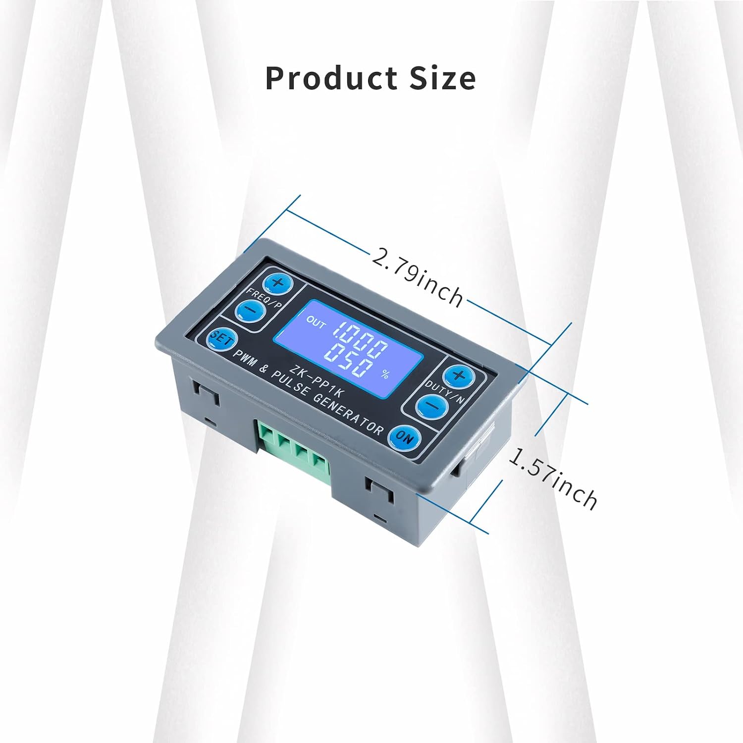
This image illustrates the physical dimensions of the ZK-PP1K module, indicating its length as approximately 2.79 inches and width as 1.57 inches.
4. Opsætning
Before operation, ensure proper power supply and connections. The ZK-PP1K requires a working voltage between 3.3V and 30V. It features anti-reverse polarity protection for safety.
4.1 Ledningsdiagram

This diagram shows the connection points for the ZK-PP1K. Connect the power input positive to V+ and power input negative to V-. The PWM output positive pole connects to PWM, and the PWM output negative pole connects to GND. An external switch signal or 3.3V level signal can be connected to the 'STOP' terminal to control PWM output ON/OFF.
- Strømindgang: Connect your DC power source (3.3V-30V) to the V+ (positive) and V- (negative) terminals.
- PWM udgang: Connect the device or circuit you wish to control to the PWM (positive) and GND (negative) output terminals.
- Ekstern kontrol (valgfri): For external ON/OFF control, connect a switch or 3.3V level signal to the 'STOP' terminal.
5. Betjeningsvejledning
The ZK-PP1K offers two main operating modes: PWM mode and PULSE mode. Only one mode can be active at a time, but you can switch between them as needed.

This image provides a comprehensive table detailing the button functions for both PWM and PULSE modes, including how to switch modes, adjust parameters, and control output.
5.1 Generel drift
- Upon powering on, the device will output a waveform.
- Bølgeformen amplitude is equal to the power supply voltage.
- If the number of output pulses reaches the set value (in PULSE mode), the output will automatically stop, and 'OUT' will disappear from the display.
- Tryk på ON key to control the presence or absence of the waveform. If 'OUT' disappears, there is no output waveform, and the output is 0.
- To restart output or recalculate the number of pulses, power cycle the device or press the ON nøgle.
5.2 PWM-tilstand
In PWM mode, you can adjust the frequency and duty cycle. The output is continuous.
- Switching to PWM Mode: Tryk længe på SÆT knappen i mere end 6 sekunder.
- Justering af frekvens: Brug FREQ/P + og FREQ/P - knapper.
- Adjusting Duty Cycle: Brug DUTY/N + og DUTY/N - knapper.
5.3 PULS-tilstand
In PULSE mode, you can set positive pulse width, negative pulse width, delay start time, and the number of pulses.
- Switching to PULSE Mode: Tryk længe på SÆT knappen i mere end 6 sekunder.
- Adjusting Positive Pulse Width: Brug FREQ/P + og FREQ/P - knapper.
- Adjusting Negative Pulse Width: Brug DUTY/N + og DUTY/N - knapper.
- Adjusting Power-on Delay: Tryk længe på SÆT button for more than 2 seconds to enter delay settings, then use FREQ/P + og FREQ/P -.
- Adjusting Number of Pulses: Tryk længe på SÆT button for more than 2 seconds to enter pulse count settings, then use DUTY/N + og DUTY/N -.

Dette billede giver en detaljeret view of the ZK-PP1K's LED display and control buttons, which are used for adjusting frequency, duty cycle, and other parameters in both PWM and Pulse modes.
5.4 Function Demonstration Video
This video demonstrates the ZK-PP1K PWM Pulse Signal Generator in operation, showing how to adjust frequency and duty cycle while observing the waveform on an oscilloscope. It highlights the device's functionality and ease of parameter adjustment.
6. Anvendelsesscenarier
- Generating square wave and rectangular wave signals.
- Controlling DC motor or stepper motor drivers.
- Applications involving servo motors, stepper motors, and electric grippers.
- Replacing PLC pulse signals in automation systems.
- Can be paired with drivers for dimming, speed regulation, and controlling solenoid valves. Note: The ZK-PP1K cannot directly drive high-current loads such as electric light motors or large solenoid valves without an appropriate driver.
7. Vedligeholdelse
To ensure the longevity and optimal performance of your ZK-PP1K PWM Pulse Signal Generator, follow these general maintenance guidelines:
- Hold enheden ren og fri for støv og snavs. Brug en blød, tør klud til rengøring.
- Undgå at udsætte enheden for ekstreme temperaturer, fugt eller direkte sollys.
- Ensure proper ventilation to prevent overheating during extended operation.
- Handle the device with care to prevent physical damage to the casing eller interne komponenter.
- Regularly check all connections for secure fit to prevent intermittent operation or short circuits.
8. Fejlfinding
If you encounter issues with your ZK-PP1K, consider the following troubleshooting steps:
| Problem | Mulig årsag | Løsning |
|---|---|---|
| Ingen skærm eller strøm | Forkert strømforsyning voltage, reverse polarity, or loose connection. | Verify power supply is within 3.3V-30V. Check wiring for correct polarity. Ensure power cables are securely connected. |
| Intet udgangssignal | Output is turned OFF, incorrect mode settings, or faulty connection to load. | Tryk på ON button to ensure output is active ('OUT' should be visible). Check mode settings (PWM/PULSE) and parameters. Verify connections to the load. |
| Incorrect frequency/duty cycle | Parameters not set correctly. | Refer to Section 5.2 (PWM Mode) or 5.3 (PULSE Mode) for correct parameter adjustment procedures. |
| Output stops prematurely in PULSE mode | Set number of pulses reached. | This is normal operation. To restart, power cycle or press the ON button. Adjust the number of pulses if continuous output is desired (set to '----' for infinite). |
9. Garanti og support
This product is typically covered by a standard return policy. Please refer to your purchase platform for specific return and warranty details. For technical support or further inquiries, please contact EC Buying customer service through the retailer where the product was purchased.
Returpolitik: A 30-day return policy is generally available for this product. Please check with your vendor for exact terms.