1. Introduktion
This manual provides detailed instructions for the installation, operation, and maintenance of your BooiParts G31T-LM V1.0 Desktop Motherboard. Please read this manual thoroughly before proceeding with installation to ensure proper setup and to prevent damage to the components.
2. Sikkerhedsoplysninger
- Afbryd altid strømforsyningen fra stikkontakten, før du installerer eller fjerner komponenter.
- Bær en antistatisk håndledsrem, eller rør ofte ved en jordforbundet metalgenstand for at aflade statisk elektricitet, før du håndterer bundkortet eller andre komponenter. Statisk elektricitet kan beskadige følsomme elektroniske dele.
- Hold bundkortet i kanterne for at undgå at berøre følsomme komponenter.
- Sørg for, at alle kabler er tilsluttet korrekt og sikkert, før du tænder for systemet.
- Udsæt ikke bundkortet for fugt eller ekstreme temperaturer.
3. Pakkens indhold
Kontroller, at alle varer er til stede i din pakke. Hvis der mangler eller er beskadigede varer, skal du kontakte din forhandler.
- BooiParts G31T-LM V1.0 Desktop Motherboard
- I/O Shield (may be included)
- SATA Data Cable (may be included)
- Brugervejledning (dette dokument)
4. Produktet er slutview
The BooiParts G31T-LM V1.0 motherboard is designed for Intel LGA 775 processors and supports DDR2 memory. Below are key components and their locations.
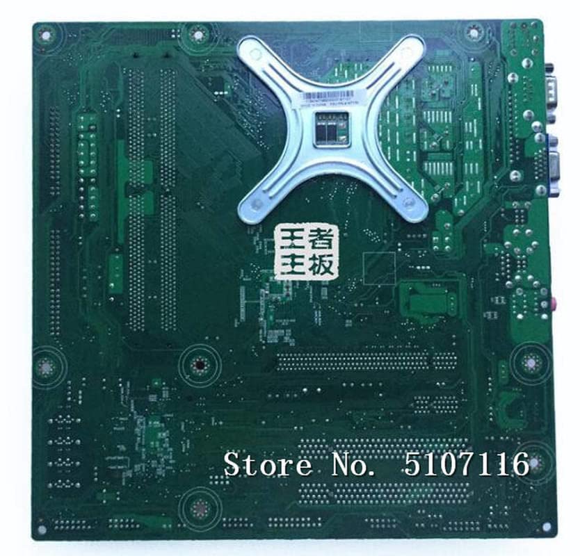
Figur 4.1: Top view of the BooiParts G31T-LM V1.0 motherboard. This image highlights the central LGA 775 CPU socket, two DDR2 RAM slots to its right, and various expansion slots (PCIe and PCI) below the CPU area. Power connectors and SATA ports are also visible along the edges.

Figur 4.2: Vinklet view of the BooiParts G31T-LM V1.0 motherboard. This perspective provides a clearer view of the rear I/O panel, including PS/2 ports, serial port, VGA output, USB ports, Ethernet port, and audio jacks. Key components like the chipset heatsink and power delivery components are also visible.
4.1 nøglekomponenter
- LGA 775 CPU Socket: For Intel Core 2 Duo and Pentium D processors.
- DDR2 DIMM-pladser: Two slots supporting up to 8GB DDR2 memory.
- PCI Express-slot: Til grafikkort.
- PCI-pladser: Til andre udvidelseskort.
- SATA-port: For connecting storage devices.
- Bagerste I/O-panel: Includes PS/2 ports, USB ports, VGA, LAN, and audio jacks.
5. Opsætning
5.1 Forberedelse
- Ensure your computer case is compatible with Micro-ATX motherboards.
- Gather all necessary components: CPU, CPU cooler, DDR2 RAM, power supply, storage devices, and graphics card (if not using integrated graphics).
5.2 CPU installation
- Find LGA 775-stikket på bundkortet.
- Løft belastningshåndtaget, og åbn CPU-sokkeldækslet.
- Juster forsigtigt CPU'en med soklen, og sørg for, at hakkene på CPU'en passer til tasterne på soklen. Tving ikke CPU'en på plads.
- Luk stikkontaktdækslet, og tryk belastningshåndtaget ned, indtil det klikker på plads.
5.3 Installation af CPU-køler
Apply thermal paste to the CPU if not pre-applied on the cooler. Install the CPU cooler according to its manufacturer's instructions, ensuring it is securely fastened and the fan cable is connected to the CPU_FAN header on the motherboard.
5.4 RAM-installation
- Åbn klipsene i begge ender af DDR2 DIMM-pladserne.
- Juster RAM-modulet med stikket, og sørg for, at hakket på modulet passer til nøglen i stikket.
- Tryk godt ned i begge ender af RAM-modulet, indtil klipsene klikker på plads.
5.5 Motherboard Installation into Case
- Installer I/O-skjoldet i den bageste åbning af computerkabinettet.
- Carefully place the motherboard into the case, aligning the screw holes on the motherboard with the standoffs in the case.
- Fastgør bundkortet med skruer. Spænd ikke for hårdt.
5.6 Tilslutning af strøm
- Tilslut 24-bens ATX-strømstikket fra din strømforsyning til den tilsvarende header på bundkortet.
- Connect the 4-pin ATX 12V power connector (CPU power) to its header near the CPU socket.
5.7 Tilslutning af lagerenheder
Connect your SATA storage devices (HDD/SSD) to the SATA port on the motherboard using a SATA data cable. Connect the power cable from your power supply to the storage device.
5.8 Tilslutning af frontpanelstik
Connect the front panel cables (Power SW, Reset SW, HDD LED, Power LED, USB, Audio) from your case to the corresponding headers on the motherboard. Refer to the motherboard's silkscreen labels for correct pin orientation.
5.9 Tilslutning af eksterne enheder
Tilslut dit tastatur, din mus, din skærm og andre eksterne enheder til de relevante porte på det bageste I/O-panel.
6. Betjeningsvejledning
6.1 Første opstart
After completing all connections, turn on your power supply and press the power button on your computer case. The system should power on, and you should see a display on your monitor. If not, refer to the Troubleshooting section.
6.2 BIOS/UEFI-opsætning
During startup, press the designated key (usually DEL or F2) to enter the BIOS/UEFI setup utility. Here you can configure system settings, boot order, and monitor hardware status.
7. Vedligeholdelse
- Rensning: Fjern regelmæssigt støv fra bundkortet og komponenterne med trykluft. Sørg for, at systemet er slukket og frakoblet, før rengøring.
- BIOS-opdateringer: Tjek producentens webwebsted for BIOS-opdateringer. Opdater kun BIOS, hvis det er nødvendigt, og følg instruktionerne omhyggeligt for at undgå systemustabilitet.
- Kabelstyring: Sørg for, at kablerne er pænt ført for at forbedre luftstrømmen og forhindre interferens.
8. Fejlfinding
8.1 Ingen strøm
- Kontroller, om strømforsyningen er tændt og korrekt tilsluttet bundkortet (24-bens og 4-bens stik).
- Sørg for, at frontpanelets strømafbryderkabel er korrekt tilsluttet bundkortets header.
- Test strømforsyningen med et andet system eller en strømforsyningstester.
8.2 Ingen visning
- Verify that the monitor is connected to the correct video output (onboard VGA or discrete graphics card).
- Genindsæt RAM-modulerne. Forkert isat RAM er en almindelig årsag til manglende visning.
- If using a discrete graphics card, ensure it is properly seated in its PCIe slot and has adequate power connected.
- Prøv at boote med kun én RAM-stick.
8.3 Systemustabilitet/nedbrud
- Tjek CPU- og GPU-temperaturerne. Overophedning kan forårsage ustabilitet.
- Sørg for, at alle drivere er opdaterede.
- Kør hukommelsesdiagnosticeringsværktøjer for at kontrollere for defekt RAM.
- Bekræft strømforsyningens watttage er tilstrækkeligt for alle komponenter.
9. Specifikationer
The following table outlines the key specifications for the BooiParts G31T-LM V1.0 Motherboard.
| Feature | Specifikation |
|---|---|
| Mærke | BooiParts |
| Modelnavn | G31T-LM V1.0 |
| CPU socket | LGA 775 |
| Kompatible processorer | Intel Core 2 Duo, Intel Pentium D |
| Chipsættype | Intel G31 |
| RAM-hukommelsesteknologi | DDR2 |
| Hukommelsespladser til rådighed | 2 |
| Hukommelseskapacitet (maks.) | 8 GB |
| Grafikkort interface | PCI Express |
| Total SATA Ports | 1 |
| Total PCIe Ports | 2 |
| Type hovedstrømstik | 24-benet |
| Kompatible enheder | Personlig computer |
| Modelnummer | T4900V 53Y3282 45C2882 |
10. Garanti og support
For garantioplysninger og teknisk support henvises til den dokumentation, der fulgte med dit køb, eller kontakt din forhandler. Gem din købsbevis til garantikrav.