
1. Introduktion
The Stemedu TFmini Plus is a compact and robust single-point ranging LiDAR module, designed for precise distance detection in various applications. Utilizing Time of Flight (ToF) principle, it offers a measurement range of 0.1m to 12m with high accuracy and a fast frame rate. This module is compatible with both UART and I2C interfaces, making it versatile for integration with microcontrollers like Arduino.
This manual provides essential information for the proper setup, operation, and maintenance of your TFmini Plus sensor.
Video: Overståetview of the Stemedu TFmini Plus Lidar Range Finder Sensor, showing its packaging and components.
2. Nøglefunktioner
- Driftsområde: 0.1m to 12m, suitable for various short to medium-range applications.
- Afstandsopløsning: 5mm, providing precise measurements.
- Central bølgelængde: 850nm.
- Robust design: IP65 rated enclosure for dust and water resistance, and passed drone-level vibration tests.
- Flexible Interfaces: Compatible with both UART and I2C communication protocols, switchable via commands.
- Høj billedhastighed: Up to 1000Hz for rapid data acquisition.
- Compact and Low Power: Small size and low power consumption for easy integration.
3. Tekniske specifikationer
| Specifikation | Værdi |
|---|---|
| Driftsområde | 0.1m ~ 12m |
| Afstandsopløsning | 5 mm |
| Central bølgelængde | 850 nm |
| Kommunikationsgrænseflade | UART, I2C |
| Billedhastighed | Op til 1000Hz |
| Beskyttelsesvurdering | IP65 (Antidust, Waterproof) |
| Pakkedimensioner | 2.4 x 2.4 x 1.2 tommer |
| Varens vægt | 0.81 ounce |
| Fabrikant | Stemedu |
| Modelnummer | LS |
| Dato først tilgængelig | 10. december 2018 |
4. Pakkens indhold
Når du åbner pakken, bør du finde følgende ting:
- 1x TFmini Plus Lidar Range Finder Sensor
- 1x Connection Cable (with JST GH1.25-4P connector)
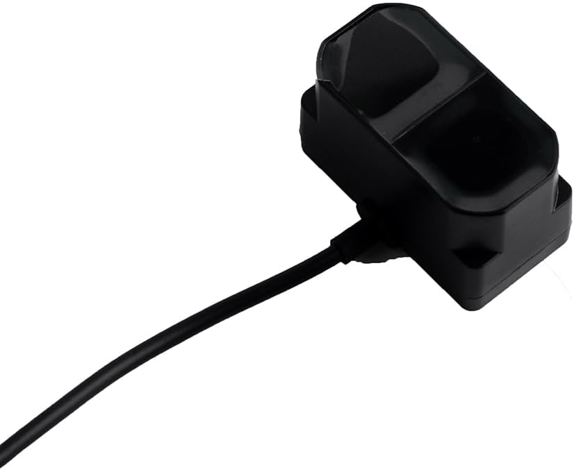
Image: The TFmini Plus Lidar sensor with its integrated connection cable.
5. Funktionsprincip
5.1 Time of Flight (ToF) Principle
The TFmini Plus operates on the Time of Flight (ToF) principle. It emits modulated near-infrared light, which is reflected by an object. The sensor then measures the phase difference between the emitted and received light waves to calculate the round-trip time. This time is directly proportional to the distance between the sensor and the detected object.
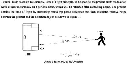
Image: Schematic diagram showing the ToF principle, where the sensor emits light (φ1) and receives reflected light (φ2) to calculate distance (D).
5.2 Range and Effectiveness
While the TFmini Plus is designed to minimize environmental influence, factors such as ambient illumination intensity and object reflectivity can affect measurement performance. The effective detection range and minimum detectable object size vary with distance.

Image: Diagram illustrating the sensor's field of view and a table detailing the minimum side length of an object for effective detection at various ranges.
6. Physical Details and Dimensions
The TFmini Plus features a compact design, making it easy to integrate into various projects. Below are the general dimensions and structure of the sensor.

Image: Detailed structural drawing of the TFmini Plus, including top, side, and front views med dimensioner.
7. Connectivity and Wiring
7.1 Pinout and Connection
The TFmini Plus uses a 4-pin connector for power and data communication. Ensure correct pin connections to avoid damage to the module or host device.
| Ingen. | Farve | Tilsvarende PIN-kode | Fungere | Kommentar |
|---|---|---|---|---|
| 1 | Rød | PIN-1 | +5V | Strømforsyning |
| 2 | Hvid | PIN-2 | RXD/SDA | Modtagelse af data |
| 3 | Grøn | PIN-3 | TXD/SCL | Overførsel af data |
| 4 | Sort | PIN-4 | GND | Jord |
7.2 Ledningsvejledning
Refer to the following diagram for proper wiring of the TFmini Plus to your host system.

Image: Detailed wiring diagram for the TFmini Plus, including pin assignments and communication protocol settings.
8. Kommunikationsprotokoller
8.1 UART and I2C Interfaces
The TFmini Plus supports both UART (Universal Asynchronous Receiver-Transmitter) and I2C (Inter-Integrated Circuit) communication. The default baud rate for UART is 115200. These interfaces can be switched using specific commands.
| Kommunikationsgrænseflade | UART | I2C |
|---|---|---|
| Standard Baud Rate | 115200 | N/A |
| Databit | 8 | N/A |
| Stop bit | 1 | N/A |
| Paritetskontrol | Ingen | N/A |
| Master/Slave-tilstand | N/A | Slave |
| Standardadresse | N/A | 0x10 |
8.2 Dataformat
The data frame transmitted by the TFmini Plus consists of 9 bytes, including distance, signal strength, temperature, and a checksum. Data is transmitted in hexadecimal format.
8.3 kommandoer
The TFmini Plus supports various commands for configuration and control. These commands allow you to obtain firmware version, set update rate, change measurement unit, set baud rate, enable/disable output, modify I2C slave address, and restore factory settings.
Refer to the detailed command table in the wiring guide image for specific command bytes and descriptions.
9. Typiske applikationer
The TFmini Plus sensor is suitable for a wide range of applications requiring accurate distance measurement:
- Dronehøjdeholdning og terrænfølgning: Provides precise height data for stable flight.
- Robotik: Obstacle avoidance, navigation, and object detection for autonomous robots.
- Smart Parking Systems: Detects vehicle presence and available parking spaces.
- Industriel automatisering: Material level detection, conveyor belt monitoring, and safety sensing.
- Sikkerhedsovervågning: Intrusion detection and area monitoring.

Image: Sensor used in a car barrier system.

Image: Sensor integration in smart parking.

Image: Sensor use in retail environments.

Image: Sensor application in industrial robotics.
10. Vedligeholdelse
To ensure optimal performance and longevity of your TFmini Plus sensor, follow these maintenance guidelines:
- Rensning: Periodically clean the sensor's optical window with a soft, lint-free cloth. Avoid abrasive materials or harsh chemicals that could scratch the lens.
- Miljøforhold: While the sensor is IP65 rated, prolonged exposure to extreme temperatures, direct sunlight, or highly corrosive environments should be avoided.
- Fysisk inspektion: Regularly check the cable and connector for any signs of wear or damage. Ensure the sensor is securely mounted.
11. Fejlfinding
If you encounter issues with your TFmini Plus, consider the following common troubleshooting steps:
- Ingen dataoutput:
- Verify power supply connections (+5V and GND).
- Check data line connections (RXD/SDA, TXD/SCL).
- Ensure the correct communication protocol (UART/I2C) and baud rate are configured on both the sensor and your host device.
- Confirm that the sensor is enabled for output via commands.
- Upræcise læsninger:
- Ensure the sensor's optical window is clean and unobstructed.
- Check for strong ambient light sources directly interfering with the sensor.
- Verify the target object is within the specified operating range and has sufficient reflectivity.
- Consider environmental factors like fog, smoke, or heavy rain, which can affect performance.
- Sensor Overheating:
- Ensure adequate ventilation around the sensor.
- Avoid operating in environments exceeding the specified temperature limits.
For further assistance, refer to the official documentation links provided in the product description or contact Stemedu customer support.
12. Garanti- og supportoplysninger
The Stemedu TFmini Plus Lidar Range Finder Sensor is covered by a standard manufacturer's warranty. For specific details regarding warranty terms, duration, and claims, please refer to the documentation included with your purchase or visit the official Stemedu webwebsted.
For technical support, additional resources, or to download the latest firmware and software tools, please visit the official Benewake website or contact Stemedu directly through their official channels. Relevant documentation can often be found at: http://en.benewake.com/download