
1. Introduktion
This manual provides detailed instructions for the installation, configuration, operation, and maintenance of the Logicbus Z109REG2-H Universal Converter. The Z109REG2-H is designed to manage and convert various analog input signals (mA, V, PT100, Pt1000, Pt500, Ni100, TCs, Ohm) into standard mA/V output signals, ensuring reliable data integrity through 3-way galvanic isolation.
2. Sikkerhedsoplysninger
Please read and understand all safety instructions before installing or operating the device. Failure to follow these instructions may result in equipment damage, personal injury, or death.
- Installation og vedligeholdelse bør kun udføres af kvalificeret personale.
- Sørg for, at strømforsyningen er afbrudt, før du foretager nogen elektriske tilslutninger.
- Verify correct wiring according to the connection diagrams to prevent damage.
- Brug ikke enheden i miljøer, der overskrider de angivne driftsforhold.
- Beskyt enheden mod fugt, støv og ekstreme temperaturer.
3. Produktet er slutview
The Z109REG2-H is a compact, DIN-rail mountable universal converter. It features clearly labeled terminal blocks for inputs, outputs, and power, along with status indicators on the front panel.
3.1. Front Panel and Connections
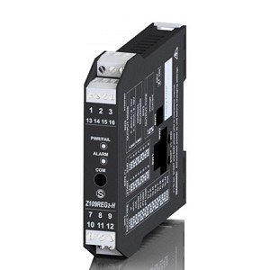
Figur 1: Front view of the Logicbus Z109REG2-H Universal Converter. This image displays the device's compact black housing, designed for DIN rail mounting. Visible on the front are two sets of screw terminals, labeled 1-3 and 13-16 at the top, and 7-9 and 10-12 at the bottom. Between these terminals, three LED indicators are present: 'PWR/TAL' (Power/Talk), 'ALARM', and 'COM' (Communication). The model number 'Z109REG-H' is also clearly printed on the lower half of the device's front face.
Frontpanelet indeholder:
- Terminalblokke: Numbered 1-3, 13-16 (top) and 7-9, 10-12 (bottom) for various input, output, and power connections.
- PWR/TAL LED: Indicates power status and communication activity.
- ALARM LED: Illuminates when an alarm condition is detected.
- COM LED: Angiver kommunikationsstatus.
- Modelnummer: Z109REG-H, identifying the device.
4. Opsætning
4.1. Montering
The Z109REG2-H is designed for DIN rail mounting. Securely attach the device to a standard DIN rail in a suitable enclosure, ensuring adequate ventilation and clearance for wiring.
4.2. Ledninger
Refer to the specific wiring diagrams provided with your product documentation for detailed connection instructions. General wiring principles are as follows:
- Strømforsyning: Connect the 85-265 V AC/DC power supply to the designated terminals. Ensure the power source matches the device's requirements.
- Indgangssignaler: Connect your analog sensor (e.g., current, voltage, thermocouple, RTD, potentiometer) to the universal input terminals. The device supports 2-wire sensor powering (20 Vdc stabilized, 20mA max with short-circuit protection).
- Udgangssignaler: Connect the standard mA/V output signals to your receiving device (e.g., PLC, DCS).
- Digital Contact: The relay (SPST) output can be configured as an ALARM or STROBE contact. Connect as required for your application.
4.3. Konfiguration
The Z109REG2-H offers multiple configuration methods:
- DIP-switche: Basic configuration for input type, START-END scale, output mode (zero elevation, scale inversion), and output voltage type (mA or V) can be set using the internal DIP-switches. Consult the product datasheet for switch settings.
- PC-software: For advanced configuration, connect the device to a PC. The software allows programming of beginning and end scale, additional input types, square root extraction, filter settings, burn-out detection, and relay output parameters.
- Handheld Device: A compatible handheld device can also be used for field configuration.
5. Betjeningsvejledning
Once properly installed and configured, the Z109REG2-H operates automatically.
- Tænd: Apply power to the device. The PWR/TAL LED should illuminate, indicating normal operation.
- Overvågning: Observe the ALARM LED for any fault conditions or out-of-scale readings. The COM LED indicates communication activity during configuration or data exchange.
- STROBE Input: If configured, the STROBE input can be used to activate the analog output on a PLC command, providing multiplexing capabilities.
6. Vedligeholdelse
The Z109REG2-H is designed for minimal maintenance. Regular checks include:
- Rensning: Keep the device clean and free from dust. Use a soft, dry cloth for cleaning. Do not use abrasive cleaners or solvents.
- Forbindelsesintegritet: Kontrollér regelmæssigt alle ledningsforbindelser for tæthed og tegn på korrosion.
- Miljøforhold: Sørg for, at driftsmiljøet forbliver inden for de angivne temperatur- og fugtighedsintervaller.
7. Fejlfinding
Hvis enheden ikke fungerer som forventet, skal du overveje følgende fejlfindingstrin:
- No Power (PWR/TAL LED off): Kontroller strømforsyningens tilslutninger og volumentage. Check for blown fuses in the power circuit.
- Incorrect Output Reading:
- Check input sensor wiring and functionality.
- Verify DIP-switch settings for input type and scale.
- Confirm PC software configuration parameters (scale, filter, burn-out).
- Ensure the output receiving device is correctly configured and calibrated.
- ALARM LED On: This indicates an out-of-scale condition or a setting error. Review input signal range and configuration settings.
- Communication Issues (COM LED): Ensure correct communication cable connection and PC software settings.
Hvis problemerne fortsætter, skal du kontakte teknisk support.
8. Specifikationer
| Feature | Specifikation |
|---|---|
| Model | Z109REG2-H |
| Inputtyper | Voltage, Current, Thermocouples, Thermoresistances (PT100, Pt1000, Pt500, Ni100), Potentiometer, Rheostat |
| Outputtyper | Isolated Analog Output (Voltage og nuværende) |
| Strømforsyning | 85-265 V AC/DC |
| Sensor Power (2-wire) | 20 Vdc stabilized, 20mA max with short-circuit protection |
| Konfiguration | DIP-switches, PC software, Handheld device |
| Galvanisk isolering | 3-way (Power supply // Input // Output) |
| Insulation (Supply to Output/Input) | 3750 Vac |
| Insulation (Output to Input) | 1500 Vac |
| Digital Contact | Relay (SPST), programmable as ALARM or STROBE |
| Dimensioner | 5 x 1 x 4 tommer (ca. 127 x 25.4 x 101.6 mm) |
| Vægt | 7.05 ounce (ca. 200 gram) |
| Fabrikant | Seneca |
9. Garantioplysninger
Warranty terms and conditions for the Logicbus Z109REG2-H Universal Converter are provided by the manufacturer, Seneca, or your authorized reseller. Please refer to the documentation included with your purchase or contact your supplier for specific warranty details and duration.
10. Teknisk support
For technical assistance, troubleshooting beyond the scope of this manual, or inquiries regarding product functionality, please contact your Logicbus supplier or the manufacturer, Seneca. Have your product model number (Z109REG2-H) and any relevant error messages or symptoms ready when contacting support.