
1. Introduktion
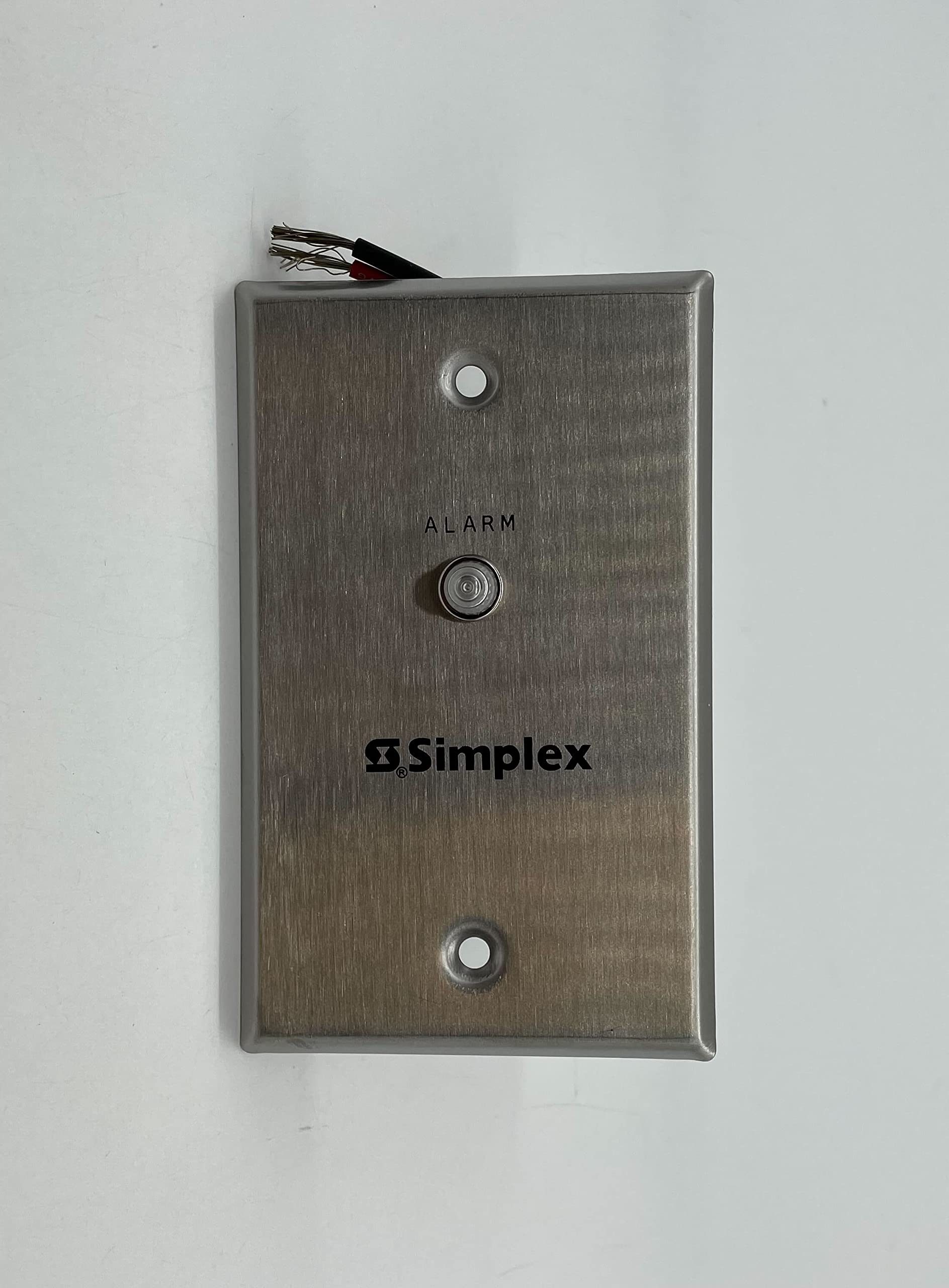
This manual provides instructions for the installation, operation, and maintenance of the Simplex 2098-9808 Remote LED Alarm Indicator. This device is designed to provide a visual alarm indication for fire safety systems, typically used in conjunction with duct detection systems or other fire alarm control panels. It features a 24V LED indicator and is intended for wall-mounted applications.
Læs venligst denne manual grundigt inden installation og ibrugtagning for at sikre korrekt funktionalitet og sikkerhed.
2. Sikkerhedsoplysninger
ADVARSEL: Installation and servicing must be performed by qualified personnel only. Disconnect all power before installing or servicing this device.
- Følg altid lokale og nationale elektriske forskrifter og regler.
- Sørg for, at strømkilden passer til enhedens lydstyrketage-krav (24V DC).
- Udsæt ikke enheden for fugt eller ekstreme temperaturer.
- Kontroller, at alle forbindelser er sikre og korrekt polariserede, før du tilslutter strømmen.
- This device is a visual indicator only and does not replace primary alarm notification appliances.
3. Opsætning og installation
The Simplex 2098-9808 Remote LED Alarm Indicator is designed for wall mounting. Ensure the mounting surface is stable and suitable for electrical installations.
3.1 Montering af indikatoren
- Select a visible location for the remote indicator, typically near the associated fire alarm device (e.g., duct detector).
- Secure the indicator plate to a standard electrical box or directly to the wall using appropriate fasteners. The unit includes mounting screws.
Figur 1: Bagside view of the Simplex 2098-9808 Remote LED Alarm Indicator. This image displays the back of the unit, revealing the red and black wiring terminals and the product label with model number 2098-9808, electrical ratings (0.0024 A at 24 VDC), and UL/cUL listings for Fire Alarm Equipment.
3.2 Ledningsforbindelser
The indicator requires a 24V DC power source. Connect the wiring as follows:
- Tilslut rød ledning to the positive (+) 24V DC output from the fire alarm control panel or associated device.
- Tilslut sort ledning to the negative (-) 24V DC output (common ground).
- Sørg for, at alle forbindelser er tætte og isolerede for at forhindre kortslutninger.
Refer to the wiring diagram of your fire alarm control panel or duct detector for specific connection points.
4. Betjening
The Simplex 2098-9808 Remote LED Alarm Indicator operates automatically in conjunction with the connected fire alarm system.
- When the associated fire alarm device (e.g., smoke detector, duct detector) enters an alarm state, it will provide 24V DC power to the remote indicator.
- The LED on the remote indicator will illuminate, providing a clear visual indication of an alarm condition at its location.
- The LED will remain illuminated as long as the alarm condition persists and power is supplied.
This indicator is designed for continuous operation when an alarm is active. It does not have user-operable controls.
5. Vedligeholdelse
The Simplex 2098-9808 Remote LED Alarm Indicator requires minimal maintenance. Regular inspections are recommended to ensure proper functionality.
- Visuel inspektion: Periodically check the indicator for any physical damage, loose connections, or obstructions that might obscure the LED.
- Funktionstest: As part of your regular fire alarm system testing, verify that the remote indicator illuminates when the associated alarm device is activated.
- Rensning: If necessary, gently wipe the surface of the indicator with a soft, dry cloth. Do not use abrasive cleaners or solvents.
Forsøg ikke at åbne eller reparere enheden. Overlad al service til kvalificeret personale.
6. Fejlfinding
If the Simplex 2098-9808 Remote LED Alarm Indicator does not function as expected, refer to the following troubleshooting guide:
| Problem | Mulig årsag | Løsning |
|---|---|---|
| LED does not illuminate during an alarm. |
|
|
| LED is always on, even without an alarm. |
|
|
For issues not covered here, or if troubleshooting steps do not resolve the problem, contact Simplex technical support or a qualified fire alarm technician.
7. Specifikationer
| Feature | Detalje |
|---|---|
| Modelnummer | 2098-9808 |
| Mærke | Simplex |
| Strømkilde | Direct wired electric (24V DC) |
| Aktuel lodtrækning | 0.0024 A ved 24 VDC |
| Alarmtype | Visual (LED) |
| Sensortype | Photoelectric (Note: This specification refers to the type of detector the indicator typically pairs with, not the indicator itself. The indicator is a visual output device.) |
| Materiale | Metal |
| Farve | Sølv |
| Dimensioner | Cirka 4 x 2 x 2 tommer (10.16 x 5.08 x 5.08 cm) |
| Varens vægt | Cirka 2.46 ounce (70 gram) |
| UPC | 643485652816 |
8. Garanti og support
For warranty information, please refer to the documentation provided with your purchase or contact Simplex directly. Specific warranty terms may vary by region and distributor.
For technical support or service inquiries, please contact your authorized Simplex dealer or visit the official Simplex webwebsted for kontaktoplysninger.