
1. Introduktion
This manual provides comprehensive instructions for the safe and efficient operation, installation, and maintenance of the Mean Well RSP-2400-24 AC to DC Power Supply. This high-performance power supply delivers a single 24 Volt output at 100 Amps, providing 2.4 Kilowatts of power. Please read this manual thoroughly before using the product.

Figur 1.1: Mean Well RSP-2400-24 AC to DC Power Supply. This image shows the overall physical appearance of the power supply unit, highlighting its robust metal casing- og terminalforbindelser.
2. Sikkerhedsinstruktioner
Always observe the following safety precautions to prevent injury or damage to the power supply:
- Ensure proper grounding before connecting the power supply.
- Brug ikke enheden i våde eller dråber.amp forhold.
- Bekræft input voltage and current ratings match your power source.
- Undgå at blokere ventilationsåbningerne for at forhindre overophedning.
- Kun kvalificeret personale bør udføre installation og vedligeholdelse.
- Afbryd strømmen, før du foretager nogen tilslutninger eller justeringer.
3. Produktfunktioner
The Mean Well RSP-2400-24 power supply incorporates several advanced features:
- AC input active surge current limiting.
- Høj effektivitet på op til 90%.
- Built-in active Power Factor Correction (PFC) function (PF>0.95).
- Comprehensive protections: short circuit, overload, over voltage, over temperatur.
- Fan alarm and forced air cooling by built-in DC fan with speed control.
- Udgang voltage trim function (20% to 110% of rated output voltagog).
- High power density: 12.5W/inch³.
- Current sharing capability for up to 2 units.
- Alarm signal output via relay contact and TTL signal.
- Output connector type: Lug terminal female.
4. Mekanisk specifikation
Detailed mechanical dimensions and component layout are provided below for installation planning.
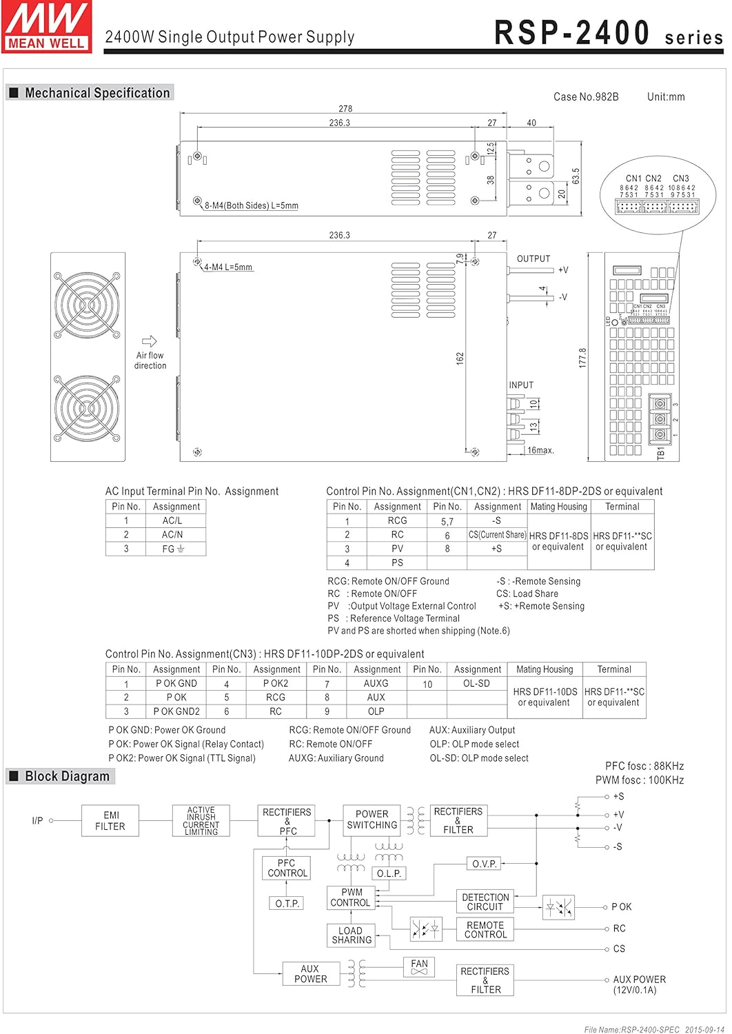
Figur 4.1: Mechanical drawing of the RSP-2400 series power supply. This diagram illustrates the physical dimensions, mounting hole locations, and general layout of the input/output terminals and cooling fans. Key dimensions are provided in millimeters.
The diagram shows the overall dimensions of 278mm (L) x 177.8mm (W) x 63.5mm (H), along with details for mounting holes (M4, L=5mm) and air flow direction for the cooling fans.
5. Opsætning og installation
5.1. AC Input Terminal Pin Assignment
Connect the AC input according to the following pin assignments:
Figur 5.1: AC Input Terminal Pin Assignment. This section of the mechanical drawing details the connections for the AC input, including AC/L, AC/N, and FG (Frame Ground) terminals.
| Pin nr. | Opgave |
|---|---|
| 1 | AC/L |
| 2 | AC/N |
| 3 | FG |
5.2. Control Pin No. Assignment
The control pins (CN1, CN2, CN3) allow for remote control and monitoring functions. Refer to the diagram for detailed assignments.
Figur 5.2: Control Pin No. Assignment for CN1, CN2, and CN3. This part of the mechanical drawing provides a detailed pinout for the control connectors, including functions like Remote ON/OFF, Current Share, and Auxiliary output.
| Pin nr. | Opgave | Parringshus | Terminal |
|---|---|---|---|
| 1 | RCG | HRS DF11-8DP-2DS eller tilsvarende | HRS DF11-**SC eller tilsvarende |
| 2 | RC | ||
| 3 | PV | ||
| 4 | PS | HRS DF11-8DS eller tilsvarende | HRS DF11-**SC eller tilsvarende |
| 5 | CS (Current Share) | ||
| 6 | +S | ||
| 7 | -S |
RCG: Remote ON/OFF Ground
RC: Fjern ON / OFF
Reporter: Udgang Voltage Ekstern kontrol
PS: Power Supply Status Signal
CS: Indlæs Del
+S, -S: Remote Sensing (Note 6)
| Pin nr. | Opgave | Pin nr. | Opgave | Pin nr. | Opgave | Parringshus | Terminal |
|---|---|---|---|---|---|---|---|
| 1 | P OK GND | 6 | RCG | 10 | OL-SD | HRS DF11-10DP-2DS eller tilsvarende | HRS DF11-**SC eller tilsvarende |
| 2 | P OK | 7 | RC | ||||
| 3 | P OK GND2 | 8 | AUX | ||||
| 4 | P OK2 | 9 | AUXG | ||||
| 5 | P OK GND |
P OK: Strøm OK Signal (relækontakt)
P OK2: Power OK-signal (TTL-signal)
AUX: Hjælpeudgang
AUXG: Hjælpegrund
OL-SD: OLP mode select
OLP: OLP mode select
5.3. Three Phase Connection
The RSP-2400 series can be configured for 3-phase power systems. Refer to the diagrams for standard configurations.

Figur 5.3: Three Phase Connection Diagrams. This image displays three different configurations for connecting the RSP-2400 units to a 3-phase power system: 3-wire 220VAC, 3-wire 220/380VAC, and 3-wire 190/110VAC systems. Each diagram shows the wiring for multiple units (Unit 1, Unit 2, Unit 3) and their connection to the R, N, T, and FG lines.
- FIG. A: 3∅ 3W 220VAC SYSTEM (STANDARD MODEL FOR STOCK): Illustrates connection for a 3-wire, 220VAC three-phase system.
- FIG. B: 3∅ 4W 220/380VAC SYSTEM: Illustrates connection for a 4-wire, 220/380VAC three-phase system.
- FIG. C: 3∅ 4W 190/110VAC SYSTEM: Illustrates connection for a 4-wire, 190/110VAC three-phase system.
6. Betjening
6.1. Remote ON/OFF Function
The power supply can be remotely turned ON or OFF by applying voltage to the control pins (CN1 & CN2 & CN3). Refer to the following table and diagrams for connection examples.
| Tilslutningsmetode | Fig. 1.2(A) | Fig. 1.2(B) | Fig. 1.2(C) |
|---|---|---|---|
| SW Logik | Udgang på | SW åben | SW åben |
| Udgang slukket | SW Luk | SW Luk |

Figur 6.1: Examples of connecting remote ON/OFF. This image provides three circuit diagrams (A, B, C) illustrating different methods for implementing the remote ON/OFF function using external voltage sources or the internal 12V auxiliary output, showing connections to AUX, RCG, RC, SW, and AUXG pins.
- (A) Using external voltage kilde: Connect an external 12V source to control the SW pin.
- (B) Using internal 12V auxiliary output: Utilize the power supply's internal 12V AUX output for control.
- (C) Using internal 12V auxiliary output: Another configuration using the internal 12V AUX output for control.
6.2. Alarmsignaludgang
The power supply provides alarm signals via P OK and P OK2 GND pins. An external voltagDer kræves en kilde til denne funktion.
| Fungere | Beskrivelse | Output of alarm (P OK, Relay Contact) | Output of alarm (P OK2, TTL Signal) |
|---|---|---|---|
| P OK | The signal is "Low" when the power supply is above 80% of the rated output voltage. | Lav (maks. 0.5V ved 500mA) | Lav (maks. 0.5V ved 10mA) |
| The signal turns to be "High" when the power supply is under 80% of the rated output voltage or Power Fail. | Høj eller åben (Ekstern anvendt voltage, 500mA maks.) | Høj eller åben (Ekstern anvendt voltage, 10mA maks.) |

Figur 6.2: Internal circuit of P OK (Relay, total is 10W) and P OK2 (Open collector method). These diagrams show the internal circuitry for the alarm signal outputs, including connections for external voltage and resistance for both P OK and P OK2.
6.3. Udgang Voltage Trim
Output voltage can be trimmed between 20% and 110% of the rated output voltage. The PV (PIN3) and PS (PIN4) of CN1 or CN2 must be disconnected if "Output Voltage TRIM" function is used. Otherwise, the internal electrical components may be damaged, and the power supply unit may thus be out of order.
Figur 6.3: Udgang Voltage Trimming. This section of the image includes a diagram showing how to add an external 1-6V external voltage for trimming, and two graphs: one illustrating output voltage vs. external voltage, and another showing output current vs. output voltage procenttage.
- Connect +S and -S to the load.
- Connect +V and -V to the load.
- Justering af output voltage is possible between 20-110% (Typ.) of the rated output which is shown in Fig. 3.2. Reducing output current is required when the output voltage is trimmed up.
6.4. Aktuel deling
Up to 2 units can share current in parallel. For optimal performance, ensure the voltage difference among each output should be minimized (less than 0.2V).

Figur 6.4: Current Sharing Connection. This diagram illustrates how to connect multiple RSP-2400 units (Master, Slave 2, Slave 3) in parallel for current sharing, showing the connections for AC/L, AC/N, FG, +V, -V, +S, and -S terminals.
- Connect +S, -S, and CS (Current Share) pins in parallel.
- The total output current must not exceed the value determined by the following equation: (Output current at parallel operation) = (Rated output per unit) × (Number of unit) × 0.9.
- For parallel operation with 3 units or more, consult the manufacturer for specific applications.
- Ensure remote sensing wires are kept at least 10 cm from input wires.
- Under parallel operation, the "output voltage trim" function is not available.
- When in parallel operation, the minimum output load should be greater than 3% of total output load (Min. Load >3% rated current per unit × number of unit).
6.5. OLP Select (Overload Protection)
The OLP (Overload Protection) mode can be selected by modifying the connector on CN3.
Figur 6.5: OLP Mode Selection. This section of the image shows two diagrams: one for removing the shorting connector on CN3 for "constant current limiting" OLP mode, and another for inserting the shorting connector on CN3 for "constant current limiting with delay shutdown after 5 seconds" OLP mode.
- Removing the shorting connector on CN3: The O.L.P. mode will be "continuous constant current limiting".
- Inserting the shorting connector on CN3: The O.L.P. mode will be "constant current limiting with delay shutdown after 5 seconds, re-power on to recover".
7. Vedligeholdelse
Regular maintenance ensures the longevity and reliable operation of your power supply.
- Rensning: Periodically clean the exterior of the unit and ventilation openings with a soft, dry cloth. Ensure the power supply is disconnected from all power sources before cleaning. Do not use liquid cleaners.
- Inspektion: Regularly inspect cables and connections for any signs of wear, damage, or loose connections.
- Ventilation: Ensure that the area around the power supply is clear and that airflow to the cooling fans is not obstructed.
- Miljøforhold: Operate the power supply within its specified temperature and humidity ranges.
8. Fejlfinding
Dette afsnit indeholder løsninger på almindelige problemer, du kan støde på.
| Problem | Mulig årsag | Løsning |
|---|---|---|
| Ingen output voltage | No AC input power; Remote ON/OFF is OFF; Internal fuse blown; Overload protection activated. | Check AC input connection and power source; Verify Remote ON/OFF settings; Contact service if fuse is suspected; Reduce load and cycle power. |
| Udgang voltage ustabil | Loose connections; Overload; Faulty load. | Check all connections; Ensure load is within specifications; Test with a different load. |
| Overophedning | Blokeret ventilation; For høj omgivelsestemperatur; Overbelastning. | Clear obstructions from vents; Ensure adequate airflow; Reduce ambient temperature; Reduce load. |
| Ventilator kører ikke | Fan failure; Unit not under sufficient load/temperature to activate fan. | Check if the unit is hot enough to require fan operation; If fan still doesn't work when hot, contact service. |
Hvis problemet fortsætter efter at have forsøgt disse løsninger, bedes du kontakte kundesupport.
9. Specifikationer
Key technical specifications for the Mean Well RSP-2400-24 AC to DC Power Supply:
| Parameter | Værdi |
|---|---|
| Modelnummer | RSP-2400-24 |
| Mærke | MENER GODT |
| Udgang Voltage | 24 volt |
| Udgangsstrøm | 100 Amps |
| Output Wattage | 2400 watt |
| Effektivitet | Op til 90 % |
| Effektfaktorkorrektion (PFC) | Active PFC, PF>0.95 |
| Dimensioner (L x B x H) | 11.02 x 7.09 x 2.56 tommer (278 x 177.8 x 63.5 mm) |
| Vægt | 7.28 pund (3.3 kilo) |
| Afkølingsmetode | Forceret luftkøling med indbygget DC blæser |
| Beskyttelser | Kortslutning, Overbelastning, Over voltage, over temperatur |
| Connector Type | Lug terminal female |
| Kompatible enheder | Personlig computer (Note: This is a general classification, actual compatibility depends on power requirements.) |
10. Garanti og support
For warranty information and technical support, please refer to the official MEAN WELL webwebstedet eller kontakt din autoriserede forhandler. Gem din købskvittering som købsbevis i tilfælde af garantikrav.
For yderligere hjælp, besøg venligst: www.meanwell.com